Hey wintermute, here's a sub-section you may want to add to the box construction post. The point here is to show how some boxes don't need bracing. They're already too well braced. This is a photo of an under-construction enclosure at FM Corbato's place. He's permitted me to use his photo.
Some boxes are self-braced
Some boxes require the construction of sophisticated internal chambers or pathways to handle the rear wave of the driver. Two examples are back-loaded horns (BLH) and MLTL (mass loaded transmission lines).
Here is a photo of a BLH under construction:
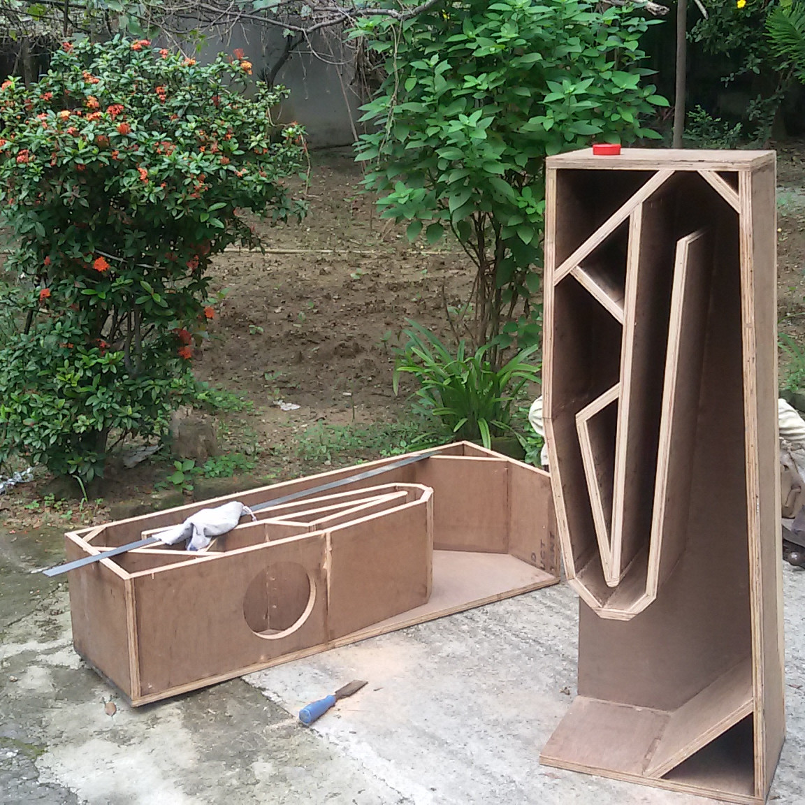
This sort of speaker needs the enclosure to have a long and tapering channel to guide the rear wave of the driver. The most convenient DIY way to make such a channel is to make a folded channel by placing partitions inside the enclosure as shown. These partitions are made of ply sheets which fix against the two sidewalls, thus bracing the sidewalls so well that no further bracing is needed.
Therefore, the entire challenge of bracing for inert enclosures is bypassed for BLH or MLTL enclosures most of the time.
Some boxes are self-braced
Some boxes require the construction of sophisticated internal chambers or pathways to handle the rear wave of the driver. Two examples are back-loaded horns (BLH) and MLTL (mass loaded transmission lines).
Here is a photo of a BLH under construction:
This sort of speaker needs the enclosure to have a long and tapering channel to guide the rear wave of the driver. The most convenient DIY way to make such a channel is to make a folded channel by placing partitions inside the enclosure as shown. These partitions are made of ply sheets which fix against the two sidewalls, thus bracing the sidewalls so well that no further bracing is needed.
Therefore, the entire challenge of bracing for inert enclosures is bypassed for BLH or MLTL enclosures most of the time.
 will do
 OK finally got around to updating. I added in an editors note as well ")
https://www.diyaudio.com/forums/multi-way/332688-design-own-speaker-scratch.html#post5668307
Tony.
https://www.diyaudio.com/forums/multi-way/332688-design-own-speaker-scratch.html#post5668307
Tony.
Wow,
Tony, tcp-ip, thank you for all this. I previously built a set of Pensil-7s that I love and am embarking now on a 2-way similar to an Econowave, but designing it myself. I've spent the last couple months sucking up information about speaker design and construction and refining my plans as I go. This thread would have been so helpful had I found it prior to xmas! Anyhow, I used some new knowledge gained in here to refine my design.
I'm going with an active cross-over care of a mini-dsp, so that simplifies certain aspects. I selected the Dayton DSA215-8, the B&C 250 compression driver, and a Faital-Pro Tractrix waveguide, along with the Dayton DSA215-PR passive radiator. I'm still uncertain about the Tractrix vs. a CD waveguide... Those maths get way too complicated. I would be interested in others' opinions on that.
Hi Tony, this is a great thread, thanks!
Pls, pls, pls, would you do a section that includes how to calculate relative acoustic offset - for dummies - like me!?
There are a few write ups out there but none really SHOW how to measure and model it.
It seems to me to be a stumbling block for great crossover design.
Thanks heaps!
Pls, pls, pls, would you do a section that includes how to calculate relative acoustic offset - for dummies - like me!?
There are a few write ups out there but none really SHOW how to measure and model it.
It seems to me to be a stumbling block for great crossover design.
Thanks heaps!
I have yet to read the offical thread, but did have some comments from the thread in the backroom where he built it. (so the quotes might be a bit different)
As one dimension of a bass reflex is elongated (keeping the volume the same) the BR transforms into a Mass Loaded Transmission Line (ML-TL), which takes advantage of the quarter-wave resonance formed as the box becomes tall & skinny. Tuning will change, and usually we can bump up the volume to get even more bass extension. A TL modeler is then needed, the leading available candidate from Leonard Audio. Transmission Line Modelling Software - diyAudio
A sealed box will also tranform into a TL, but a half-wave line. These are much longer and have a different purpose. We can discuss those later.
dave
A tall skinny cabinet may have undesirable resonances that will affect it’s sound.
As one dimension of a bass reflex is elongated (keeping the volume the same) the BR transforms into a Mass Loaded Transmission Line (ML-TL), which takes advantage of the quarter-wave resonance formed as the box becomes tall & skinny. Tuning will change, and usually we can bump up the volume to get even more bass extension. A TL modeler is then needed, the leading available candidate from Leonard Audio. Transmission Line Modelling Software - diyAudio
A sealed box will also tranform into a TL, but a half-wave line. These are much longer and have a different purpose. We can discuss those later.
dave
… bracing…
The most effective braces should be such that the ratio of dimensions of the subpanels is greater than the ratio of the original panel.
… Damping ...
A bit i wrote just the other day (part smight be a little out of context):
The need for protective gear means we don’t even try to use fibreglass insulation — except the non-itch stuff that came out of Japenese speakers as they were recycled.
Aside: Keep in mind Lojzek's "f(Hz)=172/distance; 172=half of speed of the sound (m/s); distance(m)." when thinking about how low in frequency the stuffing is effective and that if a wave passes thru (the appropriate density) a wavelength it is pretty much damped
Sealed: With any fill you typically want it to be uniform density (with a bit less around the back of the driver). In theory one can gain up to a 30% increase in apparent box volume. In practise i use 20%. I will often add a layer of denser wool or cotton felt on surfaces near the driver and those that might reflect back to the driver. We typically use ultratouch insulation (fluff it out) or well teased acoustastuff.
Reflex boxes: Typically one only lines the walls (or even just one of each parallel face) to help kill some reflections. Internal fill messes with the tuning. We use 12mm cotton felt.
Aperiodic: Can be approached as a leaky sealed box (Goodmans ARU (Ted Jordan)/Dynaco A25/Dynaudio-Scan Variovent), a reflex with heavily damped vent(Fried R/miniOnkens to some extent) or heavily damped TL with next to no terminus output (the ideal Bailey Line, but not what he built and became a craze/midTLs). Strategic type, density, & placement of damping is critical to get target function. This can be very cut-n-try… look for minimization of measured impedance peak or use GM's clik-test.
TLs: Since TLs have such a broad range of application that damping them ranges from aperiodic damping, thru uniform fiber filling dense enuff to just kill the unwanted harmonics and leave the fundemental (an idealization — there are always trade-offs) thru to just lining parts of the box. A number of tricks that TL modeling has opened up reduce the need for stuffing. We use Acoustastuff or UltraTouch insulation. And a layer of felt on surfaces near the driver.
Confusing enuff?
DIY speaker Design
Many thanks to all who have contributed to this comprehensive ideal. In a resent post I asked for help in matching drivers, a tweeter to my woofer. I see my answer is forthcoming. I've built speakers in the past with fair success, but there seemed to have faults. It must have been the lack of adequate bracing or any combination of short comings!
I hope my new build can keep pace with the input of contributions as this postings grow. One thing I would like to add is on dealing with recessing the tweeter flush to the baffle. I use the guide available at partsexpress, the Jasper circle guide. This router attachment is very accurate in cutting the flange thickness to depth. By simply locating your flanges center and adjusting depth of cut, you can route the flanges diameter first, then select the cutout for the tweeter motor/magnet. Drop in and hand cut the recesses for terminals. The guide is clearly marked in increments of 1/16" hope this helps.
Francis
Hi Guys, sorry I've been a bit pre-occupied with non-diy audio stuff, I got the next post in the series about 95% complete ages ago but that last 5% has been elusive. Life and all that!
Definitely I will put in a section on doing measurements and working out the accoustic offsets. In the interim though Mazza this will probably help a lot https://www.google.com.au/url?sa=t&...h?id=1149302&usg=AOvVaw17azVPpIXj6hirNa7YYlU9 sorry for the hideous link, google is not giving me the direct pe link.
cdrurocher, I've pretty much stuck to conventional speakers, so I'm not really good to help with horns and waveguides. Hopefully someone else can chime in!
Tony.
By "acoustic offset" I guess you mean how far back or forward the acoustic centre of each driver is with respect to the mounting plane (the front baffle)? This is the stuff the speaker design stuff call the Z axis?... would you do a section that includes how to calculate relative acoustic offset - for dummies - like me!?
Well, I've never needed to calculate or pinpoint the acoustic centres, because modern measurement and crossover modelling software takes phase andagnitide both into account and then helps you model a precise phase-coherent crossover. This way, the differences in the acoustic centres are already taken into account by the crossover simulation calculations.
I follow the following steps:
- measure the SPL of the midbass driver by keeping the mic about 40-45 inches away from the front baffle. Well, technically I measure the impulse response, and later derive the FR curve from this. It's all very easy with modern speaker measurement software. I use ARTA.
- measure the impulse response of the tweeter without changing the speaker position, mic position, the gain of the mic preamp, the volume setting of the amp... NOTHING!
With this approach, I don't need to know the relative positions of the acoustic centres on the Z axis measured, in centimetres.
My method is very commonly known among other speaker designers -- I learned it from my speaker guru in 2006. Works well.
Hi tcpip yes that is what I have generally done as well. However knowing the accoustic offset does help if you want to do certain types of modelling to experiment without building something new.
The "very" short version of Jeff's method, is that you do similar to what you do, ie take individual measurements without moving the mic, but you do a third measurement of both drivers playing together (again not moving the mic).
You then extract the minimum phase from each of the two driver measurements and put them into a crossover modeling program, loading the third measurement (of both playing together) as an overlay. Provided you have all of the offset information (ie X, Y and Z (Z being the one you don't know). Then the two drivers minimum phase measurements should add to give the same summing as the third overlay measurement.
You put in the X and Y offsets which should be well known and adjust the Z offset until the summed SPL matches the overlay, and that gives the Z offset.
Tony.
Hi tcpip yes that is what I have generally done as well. However knowing the accoustic offset does help if you want to do certain types of modelling to experiment without building something new.
Yes, you're absolutely right. I had forgotten about this use-case. But I still have some doubts about this, so I'll describe what I understand and can you please confirm or correct?
In this approach, you have to build one box with these drivers first, and then you get the relative Z offsets of the two drivers' acoustic centres, not the standalone Z offset of any one driver relative to the front baffle. Am I right? This means that either you or someone else will have to have built a box at some point with the same drivers and done these measurements. Once they're done, you get the relative Z offset, which is useful if you want to model another speaker design with the same drivers. But if you swap one of the two drivers for a third model in the new design, then your knowledge of relative Z offset is not usable? (Or is it, if one of the two drivers is a modern dome tweeter? Can we assume that the absolute Z offset of a tweeter is zero with respect to mounting plane? If yes, relative offset of the second driver will be its absolute offset.)
This was my understanding about the Z offset derivation method. Am I right?
Another doubt I have about this approach is how to remove the baffle effects from the measured SPL. (This is about the "portability" of my SPL measurements from one design to the next. It's not about Z offset derivation.) When I measure SPL of two drivers on one box, the SPL is the consequence of (i) drivers and (ii) shape and size of baffles, positions of baffle edges, finishing of baffle edges, etc. How do I use one such dataset to model the simulated SPL on a different baffle shape, size and finish?
Hmm I really need to finish the next post in the series as it addresses some of your questions
Yes the zoffset is a relative offset for those particular drivers, and yes you will need a baffle of some sort to get this initial mesasurement.
You can actually simulate the baffle response and then subtract that from your measurement to get the theoretical infinite baffle response of the driver.
With the swapping in a third driver yes you are back to square one, as the offset of this driver is likely different so you would need to do the same procedure with the new driver and the other that remained the same.
You could probably assume that the tweeter is at zero offset to the front baffle, but I doubt it would be accurate, this method really just tells you the relative Z offset between the two drivers, not how far in front of or behind the baffle either of those drivers is.
Tony.
It's quite unfortunate that we are forced to drag Z difference method here in 2019. Too many single channel measurement systems without adequate timing measurement features already sold world-wide, and more sold every day
I would write all instructions for dual channel or compatible gear, capable to measure processing and sound flying times including Z differences (as measured phase) to all directions while off-axis measurements with all radiator types and their combinations. Not just single direction with three measurements (!) assuming that it's everything what is valuable in this scene. That really sucks no matter is it some preliminary study or designing final construction.
I would write all instructions for dual channel or compatible gear, capable to measure processing and sound flying times including Z differences (as measured phase) to all directions while off-axis measurements with all radiator types and their combinations. Not just single direction with three measurements (!) assuming that it's everything what is valuable in this scene. That really sucks no matter is it some preliminary study or designing final construction.
This makes me wonder... What am I saving, or gaining, by this three-reading approach to Z offset measurement? This method forces me to measure on my intended baffle, because baffle changes will change the SPL. And it forces me do the entire exercise all over again if I change one of the drivers later, therefore making earlier measurements useless for my next project.Yes the zoffset is a relative offset for those particular drivers, and yes you will need a baffle of some sort to get this initial mesasurement.
Am I not in the same position with my 2-reading approach where I don't bother to find the Z offset at all?
Hi Kimmo, yes this is a crude method of determining z offset, but it is not meant to be the ultimate tool for designing the speaker more something to give a person something that they often do not know which they can use for experimenting in software.
I will at some point be writing a post on doing measurements using vituix cad, but it is quite a big jump from being able to get good single axis measurements to multiple off axis measurements! At this point in time I do not think I have enough experience with off axis measurements to write something useful, I have enough experience to know that I don't have enough experience! The main thread https://www.diyaudio.com/forums/multi-way/332688-design-own-speaker-scratch.html#post5668284 that this is a discussion for, is primarily aimed at people wanting to take the first steps into designing something of their own, not a definitive guide on how to build the best speaker you can
tcpip, you need to think outside the box a bit if all you are determining is the relative offset between two drivers, provided they are mounted to the same depth on any baffle, the relative Z offset will be the same. You could measure them on any baffle (boxless) to get this information (ie just one parameter, Z distance between these two drivers, you can then use that one parameter however you want. Even with manufacturers curves if you so desire
As Kimmo says, this is really only relevant for one point in space, but this is better than no info at all (especially if you are just doing some rough sims to get an idea of how something might work.
In the end what Kimmo is talking about (if you haven't checked out his vituixcad do so it is fantastic software), is going to give you the best data to model crossovers. ..
Tony.
more something to give a person something that they often do not know which they can use for experimenting in software. I will at some point be writing a post on doing measurements using vituix cad, but it is quite a big jump from being able to get good single axis measurements to multiple off axis measurements! At this point in time I do not think I have enough experience with off axis measurements to write something useful, I have enough experience to know that I don't have enough experience!
The main thread https://www.diyaudio.com/forums/multi-way/332688-design-own-speaker-scratch.html#post5668284 that this is a discussion for, is primarily aimed at people wanting to take the first steps into designing something of their own, not a definitive guide on how to build the best speaker you can tcpip, you need to think outside the box a bit
if all you are determining is the relative offset between two drivers, provided they are mounted to the same depth on any baffle, the relative Z offset will be the same. You could measure them on any baffle (boxless) to get this information (ie just one parameter, Z distance between these two drivers, you can then use that one parameter however you want. Even with manufacturers curves if you so desire As Kimmo says, this is really only relevant for one point in space, but this is better than no info at all (especially if you are just doing some rough sims to get an idea of how something might work.
In the end what Kimmo is talking about (if you haven't checked out his vituixcad do so it is fantastic software), is going to give you the best data to model crossovers. ..
Tony.
Oh, I'm already a big fan of his software. I've even given him some inputs and he's acted on them, tuning some features. I'll take a really long time to outgrow my current software stack of Unibox, Arta+Limp, and VituixCAD.In the end what Kimmo is talking about (if you haven't checked out his vituixcad do so it is fantastic software), is going to give you the best data to model crossovers. ..
Maybe the next time I'll need to look beyond these applications will be when I try an OB design.
...it is not meant to be the ultimate tool for designing the speaker
I know that difference in acoustic centers is needed in some cases. Main reason is that timing difference to common reference is not available in frequency responses. That "happens" when frequency responses are traced or measured and processed without common timing reference. Many years ago this was standard because measurement systems recorded just magnitude or analyzed RTA without phase information (with reference). Minimum phase extraction and detection of acoustic center differences were mandatory to get correct sum to at least single mic position.
This culture has (unfortunately) continued in form of USB microphones without output signal and internally connected loopback for timing reference. Technology exists but manufacturers have not implement it. Distributors sell and users recommend existing ****
Another significant challenge is that whole concept of timing reference is not that simple. We need to understand how common timing reference is locked, how timing differences are saved in impulse and frequency responses, what limits/risks exist, how measurement origin (=rotation center while off-axis sequence) and timing information in measured responses are related and how/where they can be properly adjusted. And WHY we should have measured phase with common timing reference.
I've tried to make some instructions and tools for VCAD users, but noticed that challenging and asking the same questions over and over again still continue.
Impossible to offer any single final solution for this topic. Maybe some grouping and comments that readers could identify tools and methods by suitability from narrow-minded inaccurate preliminary studies up to final accurate professional designs. But that would be just author's opinion while readers select their own gurus and methods.
The situation is close to same in 'The Speaker Building Bible' on Parts Express. Decades old methods and tools made in somewhere north of Mexico
(with few exceptions).Hello Gentlemen,
This is my first post in this thread.
I want to build a vertical WMTTMW type speaker, but I'm not in a hurry. I want to learn first. I have a UMIK-1, Holm Impulse, REW and ARTA (never used ARTA).
I have 4x tweeters and 4x midranges that sound to my liking with a simple 2nd order crossover (when used in TMW arrangement). The crossover points for these drivers should be centered around 500-700Hz, and 5kHz-6kHz.
I would like to learn how the crossover order and type (Butterworth, Bessel, so forth) affects the polar response in a WMTTMW arrangement. I think I'm open to implementing physical time alignment for the tweeters and midranges. I am open to using a digital/DSP crossover.
Thanks and apologies ahead of time for any confusion above!
I want to build a vertical WMTTMW type speaker
1/ use only 1 tweeter.
2/ given the significant driver spacing vrs a TMW you may well find steeper slopes work better at your high XO frequencies.
dave
- Home
- Loudspeakers
- Multi-Way
- Design your own speaker from scratch discussion thread