Hi tcpip long time no see ") I tried to go to your site (as in your profile) but it isn't working for me.
I tried to go to your site (as in your profile) but it isn't working for me.
Bracing is something that I've done rather crudely (or not at all) which is why I put a placeholder. I don't like to try and write about something that I'm not really experienced with. If I ever get around to redoing the cabinets for my 10" Vifa's then I will definitely get some experience though.
I'd be delighted if you provide content for the placeholder. I don't think I can change the owner of the post but I can edit and credit that it is you that has provided the content for this part
I do have a little bit that Dave (planet10) gave me, but I haven't wrapped my head around it yet! But we might put that in as well.
Tony.
I tried to go to your site (as in your profile) but it isn't working for me. Bracing is something that I've done rather crudely (or not at all
) which is why I put a placeholder. I don't like to try and write about something that I'm not really experienced with. If I ever get around to redoing the cabinets for my 10" Vifa's then I will definitely get some experience though. I'd be delighted if you provide content for the placeholder. I don't think I can change the owner of the post but I can edit and credit that it is you that has provided the content for this part
I do have a little bit that Dave (planet10) gave me, but I haven't wrapped my head around it yet! But we might put that in as well.
Tony.
Good you told me. The URL in the DIYaudio profile was wrong. Fixed it. Hope it'll work now.Hi tcpip long time no see
Good, then. How will I write the content? Will I PM you the content? I was thinking that it'll be nice if I can embed image links in the text to point to some of the cabinet details on my site, so that I can use those as examples. Don't know whether I can use all those markups in a PM. Basically, you tell me how you want me to write the stuff and I'll do it.I'd be delighted if you provide content for the placeholder. I don't think I can change the owner of the post but I can edit and credit that it is you that has provided the content for this part
i stumbled on these papers today by claus futtrup at seas fabrikker, a good read about those box issues i tried to address http://www.cfuttrup.com/blogspot/Book_05_Futtrup.pdf also look at the lossless alu box mentioned in the paper http://www.norskakustiskselskap.org/uploads/hostmote/2015/3_2_ClausFuttrup.pdf
tcpip inlining is fine but best if the images are uploaded here. I have a separate thread for uploading the images. Just to keep the clutter away from the main thread. I'll let you know what it is. PM'ing would be fine but if it is too difficult (I think there are length limits) then you could also just put it into the main thread. If you want to run it by me first you can always email it to me (send me a pm and I'll send my address.
celef, thanks for the links, I've only got part way through the first one so far, I'm always interested in how to get more accurate sims so it's interesting reading.
edit: Probably time for a link back to the main thread So you want to design your own speaker from scratch!
Tony.
celef, thanks for the links, I've only got part way through the first one so far, I'm always interested in how to get more accurate sims so it's interesting reading.
edit: Probably time for a link back to the main thread So you want to design your own speaker from scratch!
Tony.
Last edited:
Hi Wintermute,
In future can you please add MTM or MMT design post.
is M stands for mid bass driver ?. I mean is it responsible for most male female singers voice.
I am very fascinated zaph|audio website. But lot of new drivers added and technology changed after zaph|audio review of drivers 2008 (last one). If I build old one are new drivers outperform than older drivers.
Thanks,
Nag.
Yes M stands for midbass or midrange One of the issues is that because of baffle step it is hard to get a midbass that matches the sensitivity of the tweeter. Using two Midbass units (in parallel) either in MTM format or TMM (T on the top M's below) I've not seen a MMT, increases the sensitivity of the M's to better match the tweeter.
The post I'm working on at the moment will show just how much the baffle step affects the lower frequencies. It's coming along, just a bit more slowly than I would have hoped
Tony.
One of the issues is that because of baffle step it is hard to get a midbass that matches the sensitivity of the tweeter. Using two Midbass units (in parallel) either in MTM format or TMM (T on the top M's below) I've not seen a MMT, increases the sensitivity of the M's to better match the tweeter. The post I'm working on at the moment will show just how much the baffle step affects the lower frequencies. It's coming along, just a bit more slowly than I would have hoped
Tony.
Enclosure construction
Wintermute, here goes. The enclosure construction section, as promised. Hope it's good enough for your work.
Introduction to enclosure construction
My speaker guru, the friend from whom I've learned perhaps 90% of what I know about speaker design and construction, has been building speakers for a few decades. He says that the quality of a finished pair of speakers probably depends 5-10% on driver selection, 40% on enclosure construction, and the remaining 50% on crossover design. He doesn't understand why people build poorly braced enclosures and then use $300 drivers on them.
The aim of the design of the enclosures is to add the right amount of resonance at the right frequency for the woofer driver to shape the overall frequency of the speaker at the bottom end of its range. This is done by using T/S parameters, modelling the behaviour of the driver and box volume, and then arriving at the right box volume. Some speakers add to this by using bass reflex ports, passive radiators, etc. The final aim of all this designing is to tune the low frequency response of the speaker as a whole. This box modelling stage, at least for sealed boxes and bass reflex boxes, gives you the volume of the enclosure, not its shape or construction.
The aims of the construction of enclosures of conventional box speakers are
In other words, the enclosure must be completely dead or inert, and must not vibrate at all when the speaker is playing at the loudest volume you'll use it at. The best speaker enclosures therefore will be made if you build its walls with concrete or cast metal quarter inch thick. (Some pro monitor speakers are actually made with cast aluminium enclosures and are very inert.)
We are a DIY crowd, not owners of giant factory facilities in China, so we can't cast metal to make our enclosures, and concrete is a difficult material to work with. So we use MDF. It must be noted that MDF or plywood, which is used for speaker enclosures 99.999% of the time, are used because they are convenient and cost-effective, not because they are acoustically the best choice.
Once we understand this, we start working on how to make MDF or plywood enclosures which are as inert as a concrete block. The knuckle test (rap the enclosure walls with your knuckles and see if it sounds hollow) is an excellent test to see how inert speaker walls are. One of the biggest and most obvious differences between really high-end speaker enclosures ($10,000 a pair and above) and mid-range speakers (floorstanders costing $1,000-2,000 a pair) is in the inertness of the enclosures.
One word which summarises how to make inert yet hollow enclosures which don't sound hollow in the knuckle test: bracing. The basic idea of bracing is to add structures like sheets, beams, rods, inside the enclosure to prevent the surfaces of the enclosure from vibrating.
A tutorial on bracing with two examples
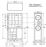
We will start with one example: a floor-stander MTM design built in the early 2000s. The drawing below shows its external shape and size (dimensions in centimetres).
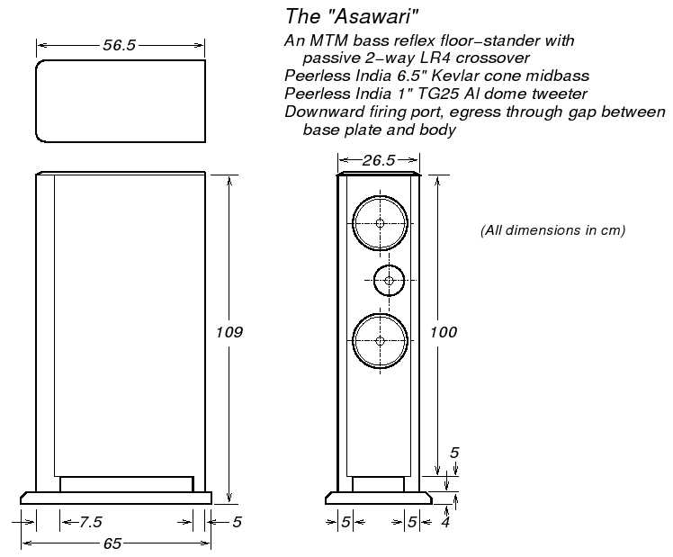
As you can see, it's a big rectangular box. Its insides is a different story. The drawing below shows a cutaway view of the internal bracing.

Basically, the (large) sidewalls of the enclosure would have vibrated loudly if they were not made rigid by putting bracing every 7-10 inches. That's what the internal structure does. The internal structure is made out of sheets of ply, which are glued together and fixed to the walls from the inside with both Araldite and wood screws. Araldite gives you the joint strength you need, but that joint itself does not form well unless you hold the adhesive surfaces pressed together hard for the first 24 hours when it sets. To ensure this, you drill holes into the walls from the outside, and screw the walls to the bracing sheets. The screws go into the bracing sheets edgeways. The screws serve little purpose once the Araldite has set, but then you can't remove them at that point -- they too are set into the Araldite and ply.
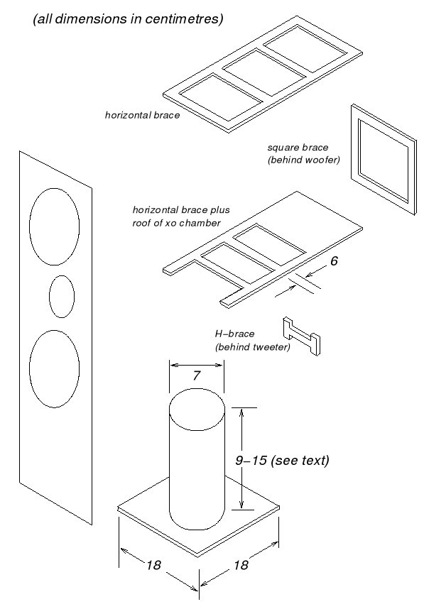
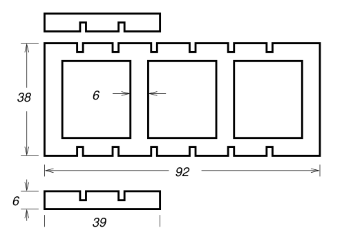
The drawing below shows the sizes and shapes of the ply sheets used to make the bracing (ignore the piece at the bottom of the drawing where a tube is fixed to a square piece of ply -- that was used for the ducted port for this speaker -- it's not part of bracing.)
Below is a photo of the half-complete enclosure with the internal bracing fitted:
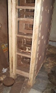 In the photo above, the front and rear baffles are yet to be fitted. This allows the carpenter free access to assemble and fix complicated internal bracing very tightly. The front and rear baffles are fixed last.
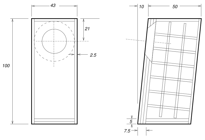
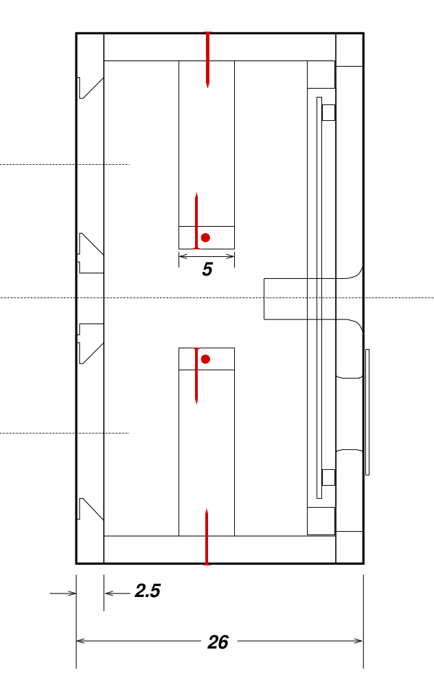
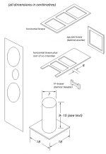
The next example is for a large woofer enclosure for a two-box, 3-way speaker design. The upper enclosure held the midrange and tweeter, and the lower enclosure held just a 10" woofer. This is a large box, a metre tall.
The internal bracing diagram for this enclosure is below:
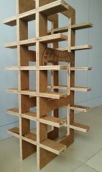
A bunch of pieces of plywood are assembled to make the internal bracing enclosure. These pieces are shown in the diagram below:
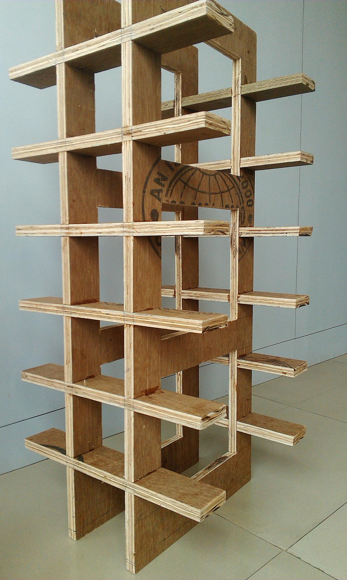
Once these pieces are assembled, they make a light, airy, very rigid standalone sub-assembly, as shown in the photo below:
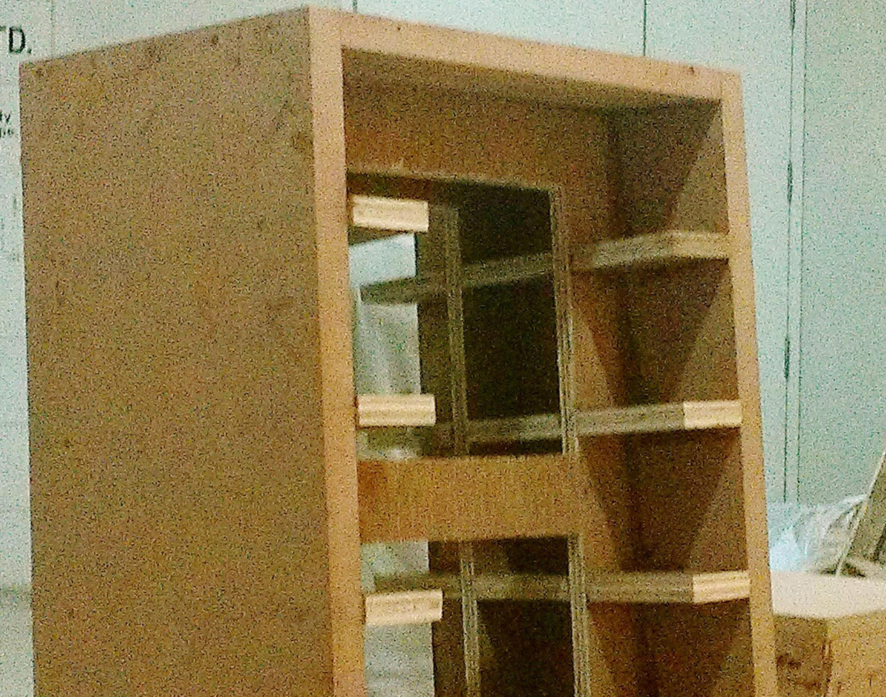
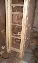
And once this sub-assembly is inserted into the shell of the enclosure, the photo below shows the half-complete enclosure with the bracing fitted:
These examples were taken from the construction of the Asawari and the construction of the Darbari, in case you want to see what those projects looked like.
My basic rules of good enclosure construction
Note that these are one DIY builder's rules. Every DIYer will have a different set of rules.
Note that bracing has no connection with the material you may choose to use to fill the enclosure. This filling absorbs standing waves, and you may use Acousta-fill, glass wool, or other fibres as you see fit. This is completely orthogonal to bracing of the enclosure surfaces.
Construction tools
Other than the usual woodworking tools, you will need a woodworking router. I will share what I have learned about routers. This will be hard to understand if you've never really seen a woodworking router in action -- a router is nothing like a drilling machine or a saw, though it is a little bit of both, functionally. I will suggest that complete newbies look for router tutorials on YouTube.
Routers have shank diameters which depend on how heavy or large the router is. You get routers which can only take up to 6mm or quarter-inch shank bits. You get 8mm shank routers. And then you get the 12mm or half-inch shank routers. These are the diameters of the shanks of the largest router bit which the router can accept.
I suggest you go for the 12mm or half-inch shank spec routers straightaway, even if you feel you don't need such a heavy-duty router, because the choice of bits you get expands sharply with the 12mm size. One of my prized bits is the 1" roundover bit, which allows me to shape an edge of my boxes with a perfect 1" radius (not 1" diameter) rounding. This bit has a cutting edge which is 2" in diameter. It will never be built with a thin shank -- it needs a half-inch shank.
You need just four bits, strictly speaking, for speaker building:
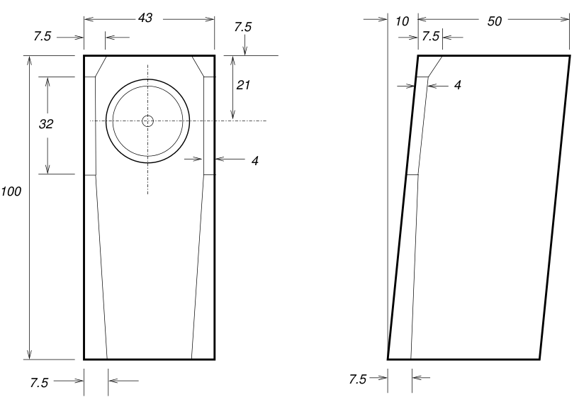
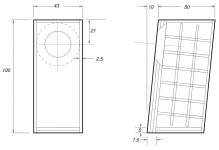
A note on bevelling the midrange cutouts from the inside: some speaker builders who I respect a lot (including John Krutke of ZaphAudio) say that the cutout of a midrange driver actually acts as a ducted port, and encourages standing waves inside it. So if you're building your front baffle with two sheets of 1" thick MDF like I do, and your midrange cutout is 5" in diameter, you are effectively creating a tube of 2" length and 5" diameter, which will generate standing waves, which will then break through the midrange cone and be audible in front of the speaker, completely messing up the midrange purity. The only way to kill those standing waves is to make the midrange cutout have sloping sidewalls, as shown in the cutaway diagram of a small MTM standmount enclosure below:
The front baffle is to the left of this diagram, and the two midbass cutouts are clearly shown. From the outer side, the cutouts have a recess of 3-4mm to allow the flanges of the drivers to sink in and mount flush with the baffle surface. From the inner side, the cutouts have been shaped with a 45-degree router bit to make them open out towards the inner side. This avoids standing wave formation. The tweeter has no rear wave, therefore there is no danger of standing waves, therefore the tweeter cutout has a recess on the front, but no sloping walls on the inside.
Mounting the crossover
This post will not talk about the design and assembly of the crossover. We will only talk here about how to physically construct it.
I find it best to fit a sheet of 6mm plywood on the inner surface of the rear baffle. I raise this sheet from the inner surface of the rear baffle by mounting the sheet on four (or six for large sheets) nylon feet of the kind carpenters fix below the legs of chairs. These light, small round feet "raise" the crossover mounting sheet about half an inch above the rear baffle surface, thus allowing me to pass wires below this sheet. The crossover components are mounted on the inner surface of this mounting sheet, and the wires which connect the crossover components to the binding posts, etc all pass in the half-inch gap between this sheet and the rear baffle.
I think my crossovers work well but are assembled in a somewhat ad hoc and primitive way with point-to-point soldering. Others use terminal blocks and do a better job.
Wintermute, here goes. The enclosure construction section, as promised. Hope it's good enough for your work.
Introduction to enclosure construction
My speaker guru, the friend from whom I've learned perhaps 90% of what I know about speaker design and construction, has been building speakers for a few decades. He says that the quality of a finished pair of speakers probably depends 5-10% on driver selection, 40% on enclosure construction, and the remaining 50% on crossover design. He doesn't understand why people build poorly braced enclosures and then use $300 drivers on them.
The aim of the design of the enclosures is to add the right amount of resonance at the right frequency for the woofer driver to shape the overall frequency of the speaker at the bottom end of its range. This is done by using T/S parameters, modelling the behaviour of the driver and box volume, and then arriving at the right box volume. Some speakers add to this by using bass reflex ports, passive radiators, etc. The final aim of all this designing is to tune the low frequency response of the speaker as a whole. This box modelling stage, at least for sealed boxes and bass reflex boxes, gives you the volume of the enclosure, not its shape or construction.
The aims of the construction of enclosures of conventional box speakers are
- to not transmit any of the rear wave sound waves of the driver through the enclosure surfaces
- to absorb direct reflections of the rear wave of the driver and not let it emerge through the driver cone as reflected waves
In other words, the enclosure must be completely dead or inert, and must not vibrate at all when the speaker is playing at the loudest volume you'll use it at. The best speaker enclosures therefore will be made if you build its walls with concrete or cast metal quarter inch thick. (Some pro monitor speakers are actually made with cast aluminium enclosures and are very inert.)
We are a DIY crowd, not owners of giant factory facilities in China, so we can't cast metal to make our enclosures, and concrete is a difficult material to work with. So we use MDF. It must be noted that MDF or plywood, which is used for speaker enclosures 99.999% of the time, are used because they are convenient and cost-effective, not because they are acoustically the best choice.
Once we understand this, we start working on how to make MDF or plywood enclosures which are as inert as a concrete block. The knuckle test (rap the enclosure walls with your knuckles and see if it sounds hollow) is an excellent test to see how inert speaker walls are. One of the biggest and most obvious differences between really high-end speaker enclosures ($10,000 a pair and above) and mid-range speakers (floorstanders costing $1,000-2,000 a pair) is in the inertness of the enclosures.
One word which summarises how to make inert yet hollow enclosures which don't sound hollow in the knuckle test: bracing. The basic idea of bracing is to add structures like sheets, beams, rods, inside the enclosure to prevent the surfaces of the enclosure from vibrating.
A tutorial on bracing with two examples
We will start with one example: a floor-stander MTM design built in the early 2000s. The drawing below shows its external shape and size (dimensions in centimetres).
As you can see, it's a big rectangular box. Its insides is a different story. The drawing below shows a cutaway view of the internal bracing.
Basically, the (large) sidewalls of the enclosure would have vibrated loudly if they were not made rigid by putting bracing every 7-10 inches. That's what the internal structure does. The internal structure is made out of sheets of ply, which are glued together and fixed to the walls from the inside with both Araldite and wood screws. Araldite gives you the joint strength you need, but that joint itself does not form well unless you hold the adhesive surfaces pressed together hard for the first 24 hours when it sets. To ensure this, you drill holes into the walls from the outside, and screw the walls to the bracing sheets. The screws go into the bracing sheets edgeways. The screws serve little purpose once the Araldite has set, but then you can't remove them at that point -- they too are set into the Araldite and ply.
The drawing below shows the sizes and shapes of the ply sheets used to make the bracing (ignore the piece at the bottom of the drawing where a tube is fixed to a square piece of ply -- that was used for the ducted port for this speaker -- it's not part of bracing.)
Below is a photo of the half-complete enclosure with the internal bracing fitted:
The next example is for a large woofer enclosure for a two-box, 3-way speaker design. The upper enclosure held the midrange and tweeter, and the lower enclosure held just a 10" woofer. This is a large box, a metre tall.
The internal bracing diagram for this enclosure is below:
A bunch of pieces of plywood are assembled to make the internal bracing enclosure. These pieces are shown in the diagram below:
Once these pieces are assembled, they make a light, airy, very rigid standalone sub-assembly, as shown in the photo below:
And once this sub-assembly is inserted into the shell of the enclosure, the photo below shows the half-complete enclosure with the bracing fitted:
These examples were taken from the construction of the Asawari and the construction of the Darbari, in case you want to see what those projects looked like.
My basic rules of good enclosure construction
Note that these are one DIY builder's rules. Every DIYer will have a different set of rules.
- Use at least 20mm thick sheet for enclosure construction. Weight matters, for obvious reasons, and the small extra cost of thicker stock is negligible compared to the cost of my time and energy.
- Use MDF or void-less ply sheets for enclosures. Void-less ply may be Baltic birch ply or very good marine ply. Void-less means there shouldn't be any small air gaps or voids in the sheet. Do not use particle board -- it's too light and low on rigidity.
- Use at least two sheets of your chosen stock for the front baffle. The absolute and complete rigidity of the front baffle has to be ensured at all costs, since it is the most prone to vibrate, and will smear the soundstage the most if it radiates sound waves.
- I use plywood for bracing even when I use MDF for the outer shell of the enclosure. Plywood, I feel, is more rigid than MDF. Bracing does not need void-free ply -- only the enclosure surfaces do. You can create a bracing structure using 2"x2" strips of timber too -- you don't need to use sheets.
- Optionally, use heavy lining for the inner surfaces of the enclosure shell. Ordinary bitumen felt is of little use -- it's too light. I have used EVA (ethyl vinyl acetate) sheets once -- each sheet was some 2-3mm thick, and had a weight of 4kg/sq-metre. I used three such sheets in a stack on the inner side-walls of the Asawari. Similarly heavy material may be used. For later builds, I have stopped looking for such linings, because I find good bracing to be more effective.
- Design your bracing so that the edges of the braces are not more than about 8" apart where they fix onto the walls.
- If you want to go super-careful, use double-sheet for the rear baffle too.
- I always round the edges of the front baffle with a 1" radius router bit, to enhance appearance and even out the edge reflections of the tweeter's output. Some people use a 45-degree bevel cut instead of a rounding cut. Some people don't do any edge treatment at all. I don't think about it any more -- I just do it blindly always nowadays, because I have the router and (hard to find) bit, and I like the final appearance.
- Tweeters must be flush mounted. This means that you not only need to make a cutout to push the tweeter in, you also need a recess on the outer surface of the front baffle so that the tweeter flange sinks into the recess and becomes flush mounted. This is very difficult to do well without a woodworking router.
- Keep the rear baffle removable. Fix the front baffle permanently. This makes the front baffle more rigid and also improves its appearance and finish. The rear baffle carries the crossover, at least in my designs, therefore you need to remove it to do internal wiring, crossover mounting, etc.
- Don't fix anything with nails. Nails come loose with time. Use wood screws wherever you may have thought of nails. And always use Araldite (any good epoxy adhesive with body) together with wood screws, not screws alone. Be obsessive about having joints which will last rigidly a hundred years. Rigidity is everything.
Note that bracing has no connection with the material you may choose to use to fill the enclosure. This filling absorbs standing waves, and you may use Acousta-fill, glass wool, or other fibres as you see fit. This is completely orthogonal to bracing of the enclosure surfaces.
Construction tools
Other than the usual woodworking tools, you will need a woodworking router. I will share what I have learned about routers. This will be hard to understand if you've never really seen a woodworking router in action -- a router is nothing like a drilling machine or a saw, though it is a little bit of both, functionally. I will suggest that complete newbies look for router tutorials on YouTube.
Routers have shank diameters which depend on how heavy or large the router is. You get routers which can only take up to 6mm or quarter-inch shank bits. You get 8mm shank routers. And then you get the 12mm or half-inch shank routers. These are the diameters of the shanks of the largest router bit which the router can accept.
I suggest you go for the 12mm or half-inch shank spec routers straightaway, even if you feel you don't need such a heavy-duty router, because the choice of bits you get expands sharply with the 12mm size. One of my prized bits is the 1" roundover bit, which allows me to shape an edge of my boxes with a perfect 1" radius (not 1" diameter) rounding. This bit has a cutting edge which is 2" in diameter. It will never be built with a thin shank -- it needs a half-inch shank.
You need just four bits, strictly speaking, for speaker building:
- a straight bit, at least 35mm or 1.5" long, to do straight cuts (cutouts with vertical walls)
- a bottom-cleaning bit of at least half-inch diameter, to cut recesses for speaker mounting (so that the speaker flange will mount flush with the surface of the front baffle)
- a 45-degree bevelled bit of 1" height (2" bit diameter) so that you can slope the sides of the cutout for your midrange drivers from the inside (more on this below).
- a 1" roundover bit, with 1" height and 2" bit diameter, to do rounding of the edges of the front baffles.
A note on bevelling the midrange cutouts from the inside: some speaker builders who I respect a lot (including John Krutke of ZaphAudio) say that the cutout of a midrange driver actually acts as a ducted port, and encourages standing waves inside it. So if you're building your front baffle with two sheets of 1" thick MDF like I do, and your midrange cutout is 5" in diameter, you are effectively creating a tube of 2" length and 5" diameter, which will generate standing waves, which will then break through the midrange cone and be audible in front of the speaker, completely messing up the midrange purity. The only way to kill those standing waves is to make the midrange cutout have sloping sidewalls, as shown in the cutaway diagram of a small MTM standmount enclosure below:
The front baffle is to the left of this diagram, and the two midbass cutouts are clearly shown. From the outer side, the cutouts have a recess of 3-4mm to allow the flanges of the drivers to sink in and mount flush with the baffle surface. From the inner side, the cutouts have been shaped with a 45-degree router bit to make them open out towards the inner side. This avoids standing wave formation. The tweeter has no rear wave, therefore there is no danger of standing waves, therefore the tweeter cutout has a recess on the front, but no sloping walls on the inside.
Mounting the crossover
This post will not talk about the design and assembly of the crossover. We will only talk here about how to physically construct it.
I find it best to fit a sheet of 6mm plywood on the inner surface of the rear baffle. I raise this sheet from the inner surface of the rear baffle by mounting the sheet on four (or six for large sheets) nylon feet of the kind carpenters fix below the legs of chairs. These light, small round feet "raise" the crossover mounting sheet about half an inch above the rear baffle surface, thus allowing me to pass wires below this sheet. The crossover components are mounted on the inner surface of this mounting sheet, and the wires which connect the crossover components to the binding posts, etc all pass in the half-inch gap between this sheet and the rear baffle.
I think my crossovers work well but are assembled in a somewhat ad hoc and primitive way with point-to-point soldering. Others use terminal blocks and do a better job.
Attachments
-
 plan.png46.2 KB · Views: 1,161
 -
 woofer-box-brace-side-2_0.jpg360.1 KB · Views: 1,137
 -
 woofer-box-braces.png8.5 KB · Views: 1,127
 -
 woofer-box-internals.png41.1 KB · Views: 1,097
 -
 woofer-box-plan.png31.1 KB · Views: 1,141
 -
 box-with-braces-2_0.jpeg14.9 KB · Views: 1,119
 -
 exploded.png31.8 KB · Views: 1,119
 -
 internals.png25.4 KB · Views: 1,134
 -
 bevelled-midrange-cutout.png19.5 KB · Views: 1,132
 -
 woofer-box-with-bracing.jpg556.4 KB · Views: 1,121
Last edited:
The router bits you need
Wintermute, this post is an appendix to the enclosure construction post.
Router bits you need
A router is essential for building good speakers.
No one taught me how to use a router, which router to buy, and what bits I need. I learned all of these by buying these things, trying them out, realising my mistakes, and wasting time and money. I actually bought two routers before I stabilised on my current (third) one. So, this post may help save your time and money.
Buy a router with a half-inch or 12mm shank specification, as I had said earlier. The bits you need are exactly four, and are shown below. I buy all my bits from reputed sellers on eBay and I've never had a lemon in my track record of at least 12 bits so far.
The straight bit
You need one bit like the ones below, with blade length at least 50% longer than the sheet thickness. My sheets are 25mm, so I use straight bits with at least 40mm long blades.

Note that the bit above does not have any ball bearings. The photo below is of a bit with a ball bearing at its tip. Avoid those. They cannot be plunged into the sheet -- they need you to drill a leader hole first before they can be inserted. This slows you down.
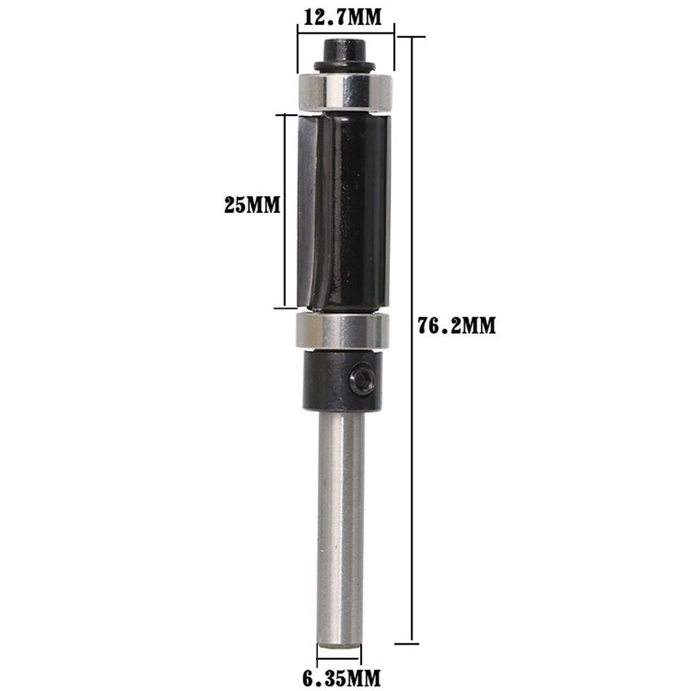
Note that straight bits are tall and slender like the Girl From Ipanema, and therefore they break. This is the only type of bit which breaks during use. Keep one or two spare bits.
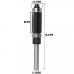
The bottom cleaning bit
This bit is needed to cut recesses to sink the speaker driver into the front baffle. As we had said earlier, tweeters must be flush mounted. I mount all drivers flush, for better looks. The bit looks very similar to the straight bit, except that it's shorter and wider. One key point about this bit is that the two blades from the two sides touch at the centre, making the bit perfect to plunge into a virgin area of the sheet and start cutting recesses.

How wide a diameter do you need? I would say anything between half inch and an inch. How long must the blades be? Ideally, longer than the deepest recess you will cut. I've never had to cut recesses deeper than about 6mm, so you can choose bits whose blades are 10-12mm long.
You use this bit in a two-step process when cutting a hole for a driver. For tweeters:
For a midrange or midbass unit:
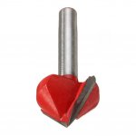
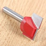
The V-groove or 45-deg bevel bit
This bit is for cutting 45-degree bevels to edges of cutouts. I use it to scallop out the cutout for a midrange or midbass driver from the inside. I have also done similar scalloping for woofer cutouts, but they are probably not needed.

This type of bit is frequently available with a ball bearing at the tip. Those are not useful.
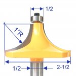
The 1" radius roundover bit
This is used (at least in my case) only for one purpose: to do roundover finishing of the outer edges of front baffles. This is one place where I don't plunge the bit into the middle of a sheet -- I always slide the bit into the edge of the sheet. Here, a ball bearing at the tip may actually be useful, and will prevent mistakes if your grip on your router shakes and the bit is in danger of cutting into the baffle.

Note that I am not endorsing any specific product or vendor. These are just handy examples.
Wintermute, this post is an appendix to the enclosure construction post.
Router bits you need
A router is essential for building good speakers.
No one taught me how to use a router, which router to buy, and what bits I need. I learned all of these by buying these things, trying them out, realising my mistakes, and wasting time and money. I actually bought two routers before I stabilised on my current (third) one. So, this post may help save your time and money.
Buy a router with a half-inch or 12mm shank specification, as I had said earlier. The bits you need are exactly four, and are shown below. I buy all my bits from reputed sellers on eBay and I've never had a lemon in my track record of at least 12 bits so far.
The straight bit
You need one bit like the ones below, with blade length at least 50% longer than the sheet thickness. My sheets are 25mm, so I use straight bits with at least 40mm long blades.
Note that the bit above does not have any ball bearings. The photo below is of a bit with a ball bearing at its tip. Avoid those. They cannot be plunged into the sheet -- they need you to drill a leader hole first before they can be inserted. This slows you down.
Note that straight bits are tall and slender like the Girl From Ipanema, and therefore they break. This is the only type of bit which breaks during use. Keep one or two spare bits.
The bottom cleaning bit
This bit is needed to cut recesses to sink the speaker driver into the front baffle. As we had said earlier, tweeters must be flush mounted. I mount all drivers flush, for better looks. The bit looks very similar to the straight bit, except that it's shorter and wider. One key point about this bit is that the two blades from the two sides touch at the centre, making the bit perfect to plunge into a virgin area of the sheet and start cutting recesses.
How wide a diameter do you need? I would say anything between half inch and an inch. How long must the blades be? Ideally, longer than the deepest recess you will cut. I've never had to cut recesses deeper than about 6mm, so you can choose bits whose blades are 10-12mm long.
You use this bit in a two-step process when cutting a hole for a driver. For tweeters:
- First, from the outer surface of the baffle, cut a recess groove (not a through-cut) using this bottom cleaning bit whose outer diameter is 1mm larger than the flange diameter of your tweeter. (100mm flange diameter is very common for dome tweeters.)
- Then, from the outer surface, use a straight bit to make a through hole of the diameter needed for tweeter to fit in.
For a midrange or midbass unit:
- First, from the outer surface of the baffle, cut a recess groove (not a through-cut) using this bottom cleaning bit, 1mm larger in diameter than the flange diameter.
- Then, from the inner side of the baffle, use the 45-degree bevel bit to make a cutout which will be a through cut, with 45-degree sloping sidewalls.
- If, like me, you use two sheets for your front baffle, then you will need to do the 45-degree cutouts in the two sheets one by one, carefully calculating the incremental diameter.
The V-groove or 45-deg bevel bit
This bit is for cutting 45-degree bevels to edges of cutouts. I use it to scallop out the cutout for a midrange or midbass driver from the inside. I have also done similar scalloping for woofer cutouts, but they are probably not needed.
This type of bit is frequently available with a ball bearing at the tip. Those are not useful.
The 1" radius roundover bit
This is used (at least in my case) only for one purpose: to do roundover finishing of the outer edges of front baffles. This is one place where I don't plunge the bit into the middle of a sheet -- I always slide the bit into the edge of the sheet. Here, a ball bearing at the tip may actually be useful, and will prevent mistakes if your grip on your router shakes and the bit is in danger of cutting into the baffle.
Note that I am not endorsing any specific product or vendor. These are just handy examples.
Attachments

Last edited:
Sorry, I'd forgotten entirely about the images thread.Thanks tcpip!
It took me four years and not finished. Either I am joke or I should quit.
andy2 I joined in 2003 to ask questions about the speaker I wanted to build from scratch. I bought the drivers in 2004, I cut all of the MDF for the cabinets and partially finished them in 2005. I finished the cabinets I think in 2009, I think the "final" version of the crossover was done in 2011, and The active crossover to the 10" woofers (always part of the plan) was finally done in 2016 (I designed it in 2010). So I wouldn't feel bad about four years!
I still have to do the proper boxes for the 10" drivers and build the BA3 amp for driving the MTM's. I also do want to do another revision of the crossover on the MTM's
Tony.
Thanks again tcpip post 10 has now been filled out with your content! I resized a few of the images (just a bit) to try and get them to format a bit better when inlined. A few the forum is just changing the aspect ratio on but if clicked on they return to correct shape.
I also changed your comment wishing you could attach the images to say to look at the router bits you need below. I'll leave the two posts above in this thread as they are the originals, and should be preserved as such I think
Now I just need to get on and finish the next post that I have been working on for what seems like forever!!
Tony.
I resized a few of the images (just a bit) to try and get them to format a bit better when inlined. A few the forum is just changing the aspect ratio on but if clicked on they return to correct shape. I also changed your comment wishing you could attach the images to say to look at the router bits you need below. I'll leave the two posts above in this thread as they are the originals, and should be preserved as such I think
Now I just need to get on and finish the next post that I have been working on for what seems like forever!!
Tony.
Thanks for sharing all this. It's always interesting to see construction techniques that different people use and compare them to one's own. I tend to use a 0.5" tall 45 deg bevel bit with a bearing on the end with a 1" thick baffle and just bevel half the backside of it. I do the hole cutout first and then bevel, which is why this works. I also use a straight bit to do the recess cutout on the front - not as clean, but it works I might have to get a bottom cleaner though, I think it would be better and faster for sure. Thanks for the idea!
I also extensively use the straight bit with the bearing on the end (aka a flush trim bit) after glue-up to make all the edges of different pieces of plywood on the outside flush with the ones they are glued to. I tend to rabbet the edges that go together, and slightly oversize the rabbets so this works fairly well.
Thanks again for taking the immense time and effort I know it takes to put your post together!
I might have to get a bottom cleaner though, I think it would be better and faster for sure. Thanks for the idea!I also extensively use the straight bit with the bearing on the end (aka a flush trim bit) after glue-up to make all the edges of different pieces of plywood on the outside flush with the ones they are glued to. I tend to rabbet the edges that go together, and slightly oversize the rabbets so this works fairly well.
Thanks again for taking the immense time and effort I know it takes to put your post together!
Thanks ILikefoodz, yes I too use the straight cut mostly, I do the rebate for the tweeter first then change the diameter to do the hole. I used a 45 deg bit with bearing on the back of my MTM's baffle for the bevel but decided it wasn't enough and used my dremel to hand craft a "better" opening...

Tony.
Tony.
Wow, thanks a lot. I hope it wasn't too difficult copy-pasting all the stuff and re-doing the formatting. And yes, please feel free to edit my text as much as you want.Thanks again tcpip post 10 has now been filled out with your content!
Yes, if you use this approach, the ball bearing at the tip will be boon instead of a problem. And if you bevel to just half depth instead of full depth, I don't think there's any problem. We don't have to do everything down to the last millimetre.Thanks for sharing all this. It's always interesting to see construction techniques that different people use and compare them to one's own. I tend to use a 0.5" tall 45 deg bevel bit with a bearing on the end with a 1" thick baffle and just bevel half the backside of it. I do the hole cutout first and then bevel, which is why this works.
The bottom cleaning bit is specially good for tweeter recesses, because those are quite wide. If I had to use my fairly narrow straight bits for the recesses, I'd probably have to make multiple circles with progressively shrinking diameters -- who has the patience for that? And then there's always the danger that the cuts won't all be at exactly the same depth, making the recess a bit uneven, resulting in some air leakage, etc.I also use a straight bit to do the recess cutout on the front - not as clean, but it works
Yes, ball bearings at the tip are very useful whenever you're finishing something from the outside. The only place where ball bearings are unusable is when you want to plunge your bit into the middle of a flat surface.I also extensively use the straight bit with the bearing on the end (aka a flush trim bit) after glue-up to make all the edges of different pieces of plywood on the outside flush with the ones they are glued to. I tend to rabbet the edges that go together, and slightly oversize the rabbets so this works fairly well.
Wow, thanks a lot. I hope it wasn't too difficult copy-pasting all the stuff and re-doing the formatting. And yes, please feel free to edit my text as much as you want.
No didn't take too long
certainly nothing in comparison to the time it would have taken you to write it! Tony.
- Home
- Loudspeakers
- Multi-Way
- Design your own speaker from scratch discussion thread