No offense, but until you show measurements that separate group delay into the components of physical distance and the 'phase growth' you speak of, the plots don't support a claim that group delay can be compensated for by delay. There's no way to know what is what.
As acknowledged, a Harsch crossover is a mixed type and order crossover that utilizes delay in it's alignment. I say it is not typical, and does not make any case whatsoever for using delay to compensate for group delay in linkwitz-riley, butterworth, or bessel crossovers.
Please show otherwise...
Oh, and another asked again please ... is your term 'phase growth' what the rest of us would call group delay, or perhaps increasing group delay?
What we are still missing are generally valid maximum figures for group delay distortion perception.
Although I have developed active rossovers with almost perfect temporal response I am convinced that absolute perfection is probably not necessary to audibly satisfy even the most transient-susceptible listeners.
The avantage of transient-improved crossovers (like the Harsch and other time-aligned topologies) over transient-perfect ones would be the easier implementation, better lobing characteristics (OK, that restriction is not valid for some digital implementations) and much relaxed driver requirements.
But I agree, group-delay compensation by applying simple delay to any old crossover topology doesn't work.
Regards
Charles
Using crossover data in post #4 and files in post #23.
It seems the same step response like mine post #23.
Today, constructing analog transient-perfect speaker is moot. Just build the best speaker you can without taking care about total phase, rather match phases of all ways perfectly (unless for D'Appolito, where zero inter-driver phase isn't the proper phase offset for correct lobing).
Just unroll the total phase by manipulating the source signal with a proper digital filter. Unless you're playback chain is completely analog this filter always can be inserted in some way with no additional complications.
Only thing you must know for this is the excess phase (the phase of the allpass function that a typical crossover represents), preferably in analytical form. Take the time inverse of its impulse response and feed that into a convolver, most software players or renderers (in case of streamers) will allow for convolver plugins.
Done, with zero cost and zero ill-effects.
I think that even if we use very long FIR filters, this should not be perceived as panacea for every situation.
Especially in present times, when the top frequency supported in our digital track is by no means 20 kHz, only much more...
The higher this frequency, the worse should be behavior of FIR filters in phase and amplitude at the bottom (not enough taps to cover this range).
To my ears only IIR filters are actually suitable for treating the low frequencies.
It seems the same step response like mine post #23.
Yes it does. There is room for improvement in your filter. Impedance at 200 Hz is unnecessary low. And try to make frd files as suggested in white paper "How to Achieve Accurate In-Room Quasi-Anechoic Free-Field Frequency Response Measurements Down to 10 Hz". Need Excel to perform merging of near field response with baffle step applied to it, and far field response, and creating frequency response tails in FRD Response blender.
This is true but it seems to be extremely individual and also depending on the source material.What we are still missing are generally valid maximum figures for group delay distortion perception.
But it's really easy to conduct your own experiments and come to conclusions.
See previous post for the prerequisite, a perfect phase-coherent and also transient-perfect speaker. Then add in a bunch of analytically derived phase distortion kernels (including the polarity inverted versions) and check if this is audible or not. There is little published research on this you we have to this our own.
Personally, I've found for example that with headphones the sensitivity to phase distortion is way lower than with speakers in a real room so I don't recommend using them (and that's why many published result may not be valid because they've been established with headphones).
There is room for improvement in your filter.
Thank you, let me how?
Every digital filter out there sounds different for some reasons, so IIR can be better than FIR in some cases.To my ears only IIR filters are actually suitable for treating the low frequencies.
Thank you, let me how?
The 150uF cap in the midrange HP is too large of a value.
After looking at data again much more closely, I'm taking back what I said. If you're only doing passive crossovers and no DSP (as I understand the OP's constraints to be), I actually recommend first-order filters and close spacing of the drivers in the vertical axis to within 1/4 wavelength of the mutual central axes at the center crossover frequency. Time alignment of all driver acoustic centers in the depth dimension will facilitate this process. The resulting sound improvement should be quite apparent if you've done due diligence in box design, driver selection, and crossover dialing-in....In order to get an ideal step response that you wanted, you have to offset the higher frequency drivers farther away from the listener to achieve flat phase to get that step response...The higher the order of the filters used, the greater the phase growth that must be compensated by adding time delays on the HF drivers.
Chris
Every digital filter out there sounds different for some reasons, so IIR can be better than FIR in some cases.
I really have to disagree that every digital filter sounds different...that's a heck of a broad statement !
FWIW, I've worked with at least 4 major DSP platforms comparing crossovers and filters, and find far fewer variances than folks talk about.
I know in the early days of digitally replicated IIR, things were a bit wild and woolly. But those days appear to be gone.
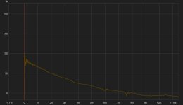
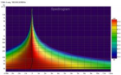
Another FWIW....an example of why I keep trying to encourage folks towards FIR and lin phase....
here's a 4-way's step and a spectrogram ....
Attachments
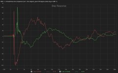
I'd like to illustrate the effect of using delay only (like moving the HF driver backwards) on the step response. The plot below shows an ESS AMT-1 on top of a Cornwall bass bin, both time aligned and with a time delay equal to 90 degrees of phase lag at the 800 Hz crossover frequency (312.5µs) or about 4.25 inches (10.8 cm) of set back of the AMT-1 relative to its time aligned position. The red trace is time aligned, and the green trace has an additional 90 degrees worth of time delay added to the AMT-1 (HF) channel--the red trace is offset by -1 ms for clarity:
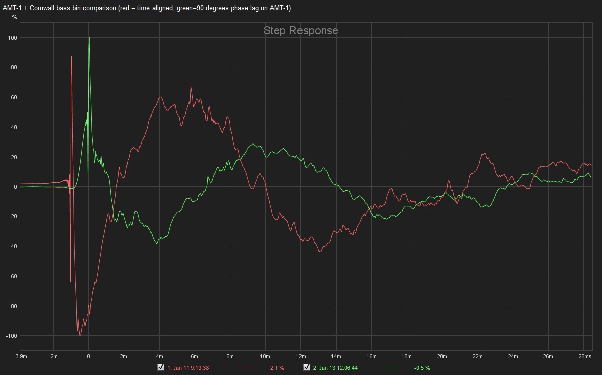
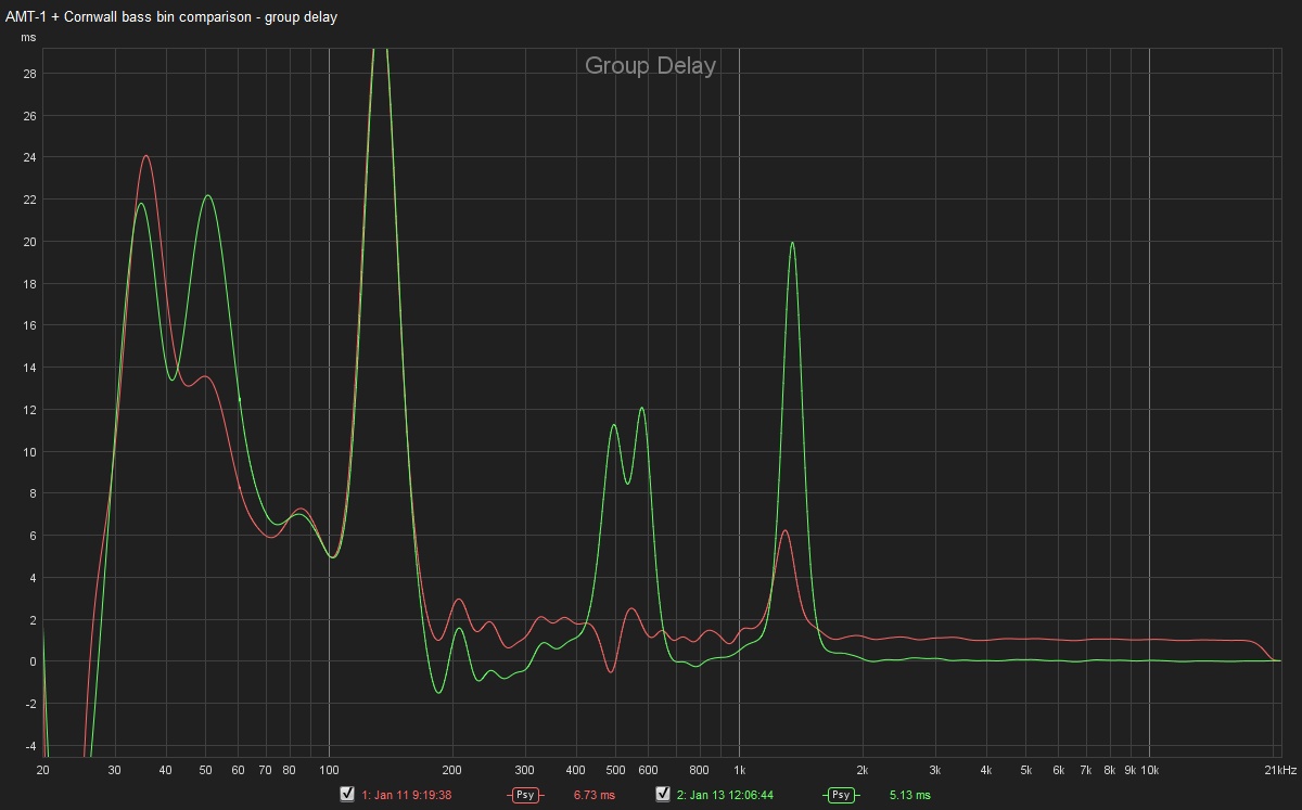
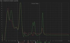
The point is that simple time delay offset can mimic a perfect step response, but with the added price of greater group delay above and below the crossover frequency (red = time aligned, green = 90 degrees HF phase lag time delay at 800 Hz):
Chris
The point is that simple time delay offset can mimic a perfect step response, but with the added price of greater group delay above and below the crossover frequency (red = time aligned, green = 90 degrees HF phase lag time delay at 800 Hz):
Chris
Attachments
Last edited:
The point is that simple time delay offset can mimic a perfect step response, but with the added price of greater group delay above and below the crossover frequency (red = time aligned, green = 90 degrees HF phase lag time delay at 800 Hz):

Chris
Hi Chris,
I'd say the 'time-aligned-only' red trace in your first graph that I didn't repost, has a clearly superior step response ... although the time alignment still needs some small adjustment.
I do not see a significant greater group delay with the red trace in the Group Delay graph above...red appears to look much better...???
Green's phase trace must look really wonky....can you show it?
FWIW, I've found that using time alignment via peak energy times gives me similar rapid oscillations in a step response, prior to the step settling into its desired triangular shape.
Time alignment via intitial rise time (found using bandpass filtered impulse responses) usually cleans up the 'pre-step' oscillations.
My comments were actually directed at the OP...not the "FIR filter enthusiasts" that seem to have seized upon this thread (for reasons unknown).
IIRC, the OP mentioned nothing about digital filtering at all--merely posting a schematic of his passive crossover filters, asking how to achieve better step response.
I'd actually recommend to those that consistently want to talk about FIR filters to the exclusion of passive crossover filters and their real-world implementation to move to another thread more suited to those needs to elaborate on those type of filters. I think the OP would probably appreciate it...")
Chris
IIRC, the OP mentioned nothing about digital filtering at all--merely posting a schematic of his passive crossover filters, asking how to achieve better step response.
I'd actually recommend to those that consistently want to talk about FIR filters to the exclusion of passive crossover filters and their real-world implementation to move to another thread more suited to those needs to elaborate on those type of filters. I think the OP would probably appreciate it...
Chris
- Status
- This old topic is closed. If you want to reopen this topic, contact a moderator using the "Report Post" button.
- Home
- Loudspeakers
- Multi-Way
- How to improve step response