First of all.......
It took some time, about a year, before I was confident enough for posting this. You might view it as a small addition to Linkwitz' work.
This idea I will share here because of a couple of things:
- Sharing is caring!
- I want everybody to be able to enjoy what I have enjoyed.
- If it is implemented more, the hardware (DSP etc) will become better suited for the topology, and therefore more people might enjoy it.
The problem...............
There always was something for me in a 2-way, that a 3-way (or more) couldn't do, sound wise. It might have measured quite OK, but something about a 2-way sounded a bit more... correct in a way? Better stereo image? Difficult to put a finger on when I started playing with crossovers.
Anyhow, just like there are people who only like fullrange, there are people who like 2-ways. 3-ways have been called 'difficult to do right' and 4-way or more 'virtually impossible' by some. When I started my 6-way project a couple of years ago, people thought I was insane. I might be to some degree but in my struggle I have tackled a problem that also exists in 3 and 4-way designs.
Investigating the "problem"....
To keep it simple, we will stick with LR filtering. You might however, find that the general idea of the solution might apply to other types of filters too.
If you take a look on this page you might notice that shifting crossovers close together creates a problem in the response. As Linkwitz put it:
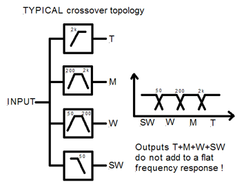
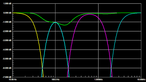
Not a flat response... It'll look like this:
And Linkwitz provided a few possible solutions for it, like adjusting the level of the effected channels:
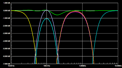
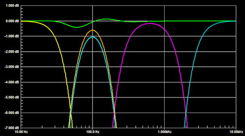
Or like cascading the filter:
Which results in the following response:
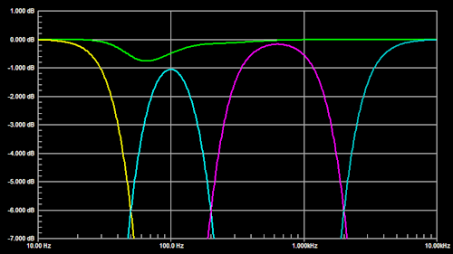
When cascading filters, Linkwitz also proposes adjusting the gains for further improvement.
Now this really grinds my gears....
Linkwitz was really on to something here. The response of the system has improved a lot versus the first example in this post. But why? Because of the phases being more coherent across the drivers. The graphical explanation of mr Linkwitz ends here.
So why not expand this idea, and use it multiple times across the speaker, to flatten the response even more? Well...
Linkwitz speaks about an 'all-pass' filter that can be added on the SW to make it integrate perfectly with the rest of the system.
However my findings show me that this doesn't have to be an all-pass filter. In fact, I only tried this with traditional filters.
And also, it doesn't have to be limited to the subwoofer only.
And also, it can be used if the driver doesn't display some 'strange responses' as Linkwitz put it.
Aaaaand my findings say that it's not exclusive to -12dB and up, but has great effects even UNDER these levels! Yes!
What I'm saying is that to strive for the most perfect phase and level response of the filter, it means that ALL filters have to be applied in some way to ALL units.
This way, no unit, anywhere, in the whole system, will EVER be out of phase with ANY other unit in the system. No loss of energy, anywhere.
You see my enthousiasm here was fired up because of hearing a difference in the sound. It definately gave me that '2-way sound', with a 4-way?!?
Before you think: "How will my midrange ever afect my subwoofer?"
Think about this: do you care about your unit having less then -12dB of distortion? Then you should also care about phase distortion caused by your filter, in this case, anywhere below -12dB. Would you be OK with phase distortion being -20dB, -30dB, -70dB, or do you strive for it to be non-existant alltogether?
HOW did I approach it?
First of all, I created this topology digitally, in a DSP. If built electrically, it'd sure be table-sized. I am no expert, so I will explain the steps I took to achieve it.
1: Shape the response of each driver individually. Your target is the ideal crossover response you want for it, eg an LR24 slope.
2: Place microphone on listening spot and time-align the units. I started with my subwoofer at zero delay, working up to the tweeter (ear level).
3: This is the point where we are going to take a different route than Linkwitz'.
With a list of your crossovers, you can make a table of how to implement the crossovers on ALL the drivers.
EG:
100Hz, 250Hz, 1000Hz
S: LP100, LP250, LP1000
W: HP100, LP250, LP1000
M: HP100, HP250, LP1000
T: HP100, HP250, HP1000
You see here, all crossovers are afecting every unit.
If you use more channels, your table may look different.
4: Adjust gains
An example I modeled with VituixCAD:

After sharing this with a couple of audio-minded friends we all agreed that we found that the speakers sounded better.
Subjectively, the sound is more clear. The stereo imaging improved a lot. We felt like we were listening less to the crossovers and more to the actual sound. It became extremely difficult to tell which sounds came from which units, as they all blend in much better.
Excited as we were about it, I e-mailed mister Linkwitz last year. Sadly, he didn't have enough time to reply to my e-mail. I would have loved his thoughts on this.
Please keep in mind:
I hestitated for a year to post this. I am just a car mechanic, I have no degrees in anything, just love playing with technical toys like speakers or computers for what that's worth. It's just that, I'd like other people to experience the difference too, because it was so evident for me and my friends. If you have the time to try this out on your system, please do, and tell me if you liked it too. Tell me I'm not mad for 'imagining' this.
Your friend,
Robbin
It took some time, about a year, before I was confident enough for posting this. You might view it as a small addition to Linkwitz' work.
This idea I will share here because of a couple of things:
- Sharing is caring!
- I want everybody to be able to enjoy what I have enjoyed.
- If it is implemented more, the hardware (DSP etc) will become better suited for the topology, and therefore more people might enjoy it.
The problem...............
There always was something for me in a 2-way, that a 3-way (or more) couldn't do, sound wise. It might have measured quite OK, but something about a 2-way sounded a bit more... correct in a way? Better stereo image? Difficult to put a finger on when I started playing with crossovers.
Anyhow, just like there are people who only like fullrange, there are people who like 2-ways. 3-ways have been called 'difficult to do right' and 4-way or more 'virtually impossible' by some. When I started my 6-way project a couple of years ago, people thought I was insane. I might be to some degree but in my struggle I have tackled a problem that also exists in 3 and 4-way designs.
Investigating the "problem"....
To keep it simple, we will stick with LR filtering. You might however, find that the general idea of the solution might apply to other types of filters too.
If you take a look on this page you might notice that shifting crossovers close together creates a problem in the response. As Linkwitz put it:
Not a flat response... It'll look like this:
And Linkwitz provided a few possible solutions for it, like adjusting the level of the effected channels:
Or like cascading the filter:
Which results in the following response:
When cascading filters, Linkwitz also proposes adjusting the gains for further improvement.
Now this really grinds my gears....
Linkwitz was really on to something here. The response of the system has improved a lot versus the first example in this post. But why? Because of the phases being more coherent across the drivers. The graphical explanation of mr Linkwitz ends here.
So why not expand this idea, and use it multiple times across the speaker, to flatten the response even more? Well...
Linkwitz speaks about an 'all-pass' filter that can be added on the SW to make it integrate perfectly with the rest of the system.
However my findings show me that this doesn't have to be an all-pass filter. In fact, I only tried this with traditional filters.
And also, it doesn't have to be limited to the subwoofer only.
And also, it can be used if the driver doesn't display some 'strange responses' as Linkwitz put it.
Aaaaand my findings say that it's not exclusive to -12dB and up, but has great effects even UNDER these levels! Yes!
What I'm saying is that to strive for the most perfect phase and level response of the filter, it means that ALL filters have to be applied in some way to ALL units.
This way, no unit, anywhere, in the whole system, will EVER be out of phase with ANY other unit in the system. No loss of energy, anywhere.
You see my enthousiasm here was fired up because of hearing a difference in the sound. It definately gave me that '2-way sound', with a 4-way?!?
Before you think: "How will my midrange ever afect my subwoofer?"
Think about this: do you care about your unit having less then -12dB of distortion? Then you should also care about phase distortion caused by your filter, in this case, anywhere below -12dB. Would you be OK with phase distortion being -20dB, -30dB, -70dB, or do you strive for it to be non-existant alltogether?
HOW did I approach it?
First of all, I created this topology digitally, in a DSP. If built electrically, it'd sure be table-sized. I am no expert, so I will explain the steps I took to achieve it.
1: Shape the response of each driver individually. Your target is the ideal crossover response you want for it, eg an LR24 slope.
2: Place microphone on listening spot and time-align the units. I started with my subwoofer at zero delay, working up to the tweeter (ear level).
3: This is the point where we are going to take a different route than Linkwitz'.
With a list of your crossovers, you can make a table of how to implement the crossovers on ALL the drivers.
EG:
100Hz, 250Hz, 1000Hz
S: LP100, LP250, LP1000
W: HP100, LP250, LP1000
M: HP100, HP250, LP1000
T: HP100, HP250, HP1000
You see here, all crossovers are afecting every unit.
If you use more channels, your table may look different.
4: Adjust gains
An example I modeled with VituixCAD:
After sharing this with a couple of audio-minded friends we all agreed that we found that the speakers sounded better.
Subjectively, the sound is more clear. The stereo imaging improved a lot. We felt like we were listening less to the crossovers and more to the actual sound. It became extremely difficult to tell which sounds came from which units, as they all blend in much better.
Excited as we were about it, I e-mailed mister Linkwitz last year. Sadly, he didn't have enough time to reply to my e-mail. I would have loved his thoughts on this.
Please keep in mind:
I hestitated for a year to post this. I am just a car mechanic, I have no degrees in anything, just love playing with technical toys like speakers or computers for what that's worth. It's just that, I'd like other people to experience the difference too, because it was so evident for me and my friends. If you have the time to try this out on your system, please do, and tell me if you liked it too. Tell me I'm not mad for 'imagining' this.
Your friend,
Robbin
An interesting idea.
I only see the point when the drivers frequency is tuned completely flat before you apply the filter. For example, the sub should be completely flat over 10kHz, which, even if possible, would only work at a very narrow listening point.
Or the operation of the tweeter at 120Hz is almost impossible. I understand that this band is ultimately filtered out, but you want to control it with great precision that seems to me to be quite utopian.
For me this is my first run.
In any case, it would be good to see measurements if you have already worked on the construction.
Last edited:
Yes, flattening the drivers response is exactly what I do before applying the filter. It makes it easyer to achieve filter slopes and makes the slope more acurate down under.
And a tweeter operating at 120Hz is not very common. It should only show in modeling as a rimple at the lower units. Adding the filter however ensures uniformity of the filter phases as a total system.
In stead of thinking 'why add this filter' one could also say 'why not?' if DSP power is readily available.
Measuring data I don't have at hand right now. I might get a friend to post some of his measurements though.
You are certainly not mad for thinking about this Robbintip, in fact I'd say you are well on the way to enlightenment 
Leaving aside the realities of driver responses etc. the sum of each crossover (LP + HP) can be represented as an allpass filter.
The goal is to have all the drivers operating in phase, which means that all the drivers must be subject to the same phase response through the filter (again, assuming otherwise perfectly flat driver responses).
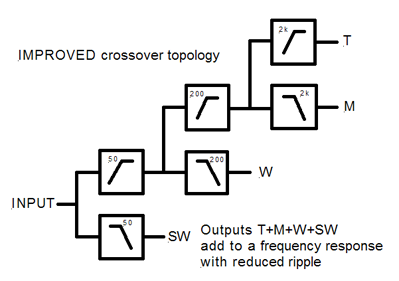
In the "IMPROVED crossover topology" sketch this is achieved by adding a suitable 2kHz allpass filter to the W and both a 200Hz AND a 2kHz allpass to the SW. Many times you can also get away with reusing LP blocks if allpass filters are not available in your chosen processing toolchain.
Vertically aligning these allpass filter blocks below the corresponding crossover blocks even makes the whole thing *look* logical.
Leaving aside the realities of driver responses etc. the sum of each crossover (LP + HP) can be represented as an allpass filter.
The goal is to have all the drivers operating in phase, which means that all the drivers must be subject to the same phase response through the filter (again, assuming otherwise perfectly flat driver responses).
In the "IMPROVED crossover topology" sketch this is achieved by adding a suitable 2kHz allpass filter to the W and both a 200Hz AND a 2kHz allpass to the SW. Many times you can also get away with reusing LP blocks if allpass filters are not available in your chosen processing toolchain.
Vertically aligning these allpass filter blocks below the corresponding crossover blocks even makes the whole thing *look* logical.
Last edited:
Very good thread!
I'm following this approach (precision phase matching of all ways) for a long time and always found this sounds best.
Cascading only works when the XO-points are far apart (so that drivers are at least 20dB down at the next XO-point), otherwise there will be magnitude errors. Typically this is still irrelevant but in theory allpass circuits must then be used to get the phases identical (and hence, a flat amplitude sum).
Last edited:
Sure, we're talking acoustic target functions here, not electrical filter responses.I only see the point when the drivers frequency is tuned completely flat before you apply the filter
The key point is: Loudspeaker/Crossover design *must* start with defining target functions. If you don't have a clear goal you won't arrive at a proper solution.
Synthesis of the needed electrical filters is then just some boring engineering task once the drivers have been measured in-situ.
Congrats! You're way ahead of some of "leading industry designers" that are phase-blind (don't know how to measure it let alone define proper targets. At best they strive for sufficient cancellation at the XO-point when a driver is inverted).What I'm saying is that to strive for the most perfect phase and level response of the filter, it means that ALL filters have to be applied in some way to ALL units.
Last edited:
configuring hp lp elements in a crossover network
for a 2-way set up, there is one method, both lp and hp fed from the input
for a 3-way setup, there are 3 configurations that give hp/bp/lp outputs,
however if the 3 possible circuits are simulated you will see the amplitude outputs are the same, but the phases are not.
once you have selected the "correct" 3-way configuration, when combined with the speakers, your acoustic amplitude and phase will be wrong (unless you have those super wide bandwidth drivers which dont exist)
to fix this, the hp/lp filter elements must take into account each drivers response so in effect the hp/lp element does not have the textbook response, but is a conjugate filter so that the drivers ascoustic output follows the textbook response.
lastly the speakers output phase wont track again due to delays introduced by the crossover itself and also when the speakers are (usally) mounted on the same plane.
to fix that, a delay can be added to the hp branch.
I commend you on your analysis, however, I must point out that you have developed an improvement on a solution for an "invented problem".
It really bothered me that SL made such a big deal about the cascade arrangement of filters on his web site. His analysis seemed rather pointless, because...
HE DID NOT INCLUDE THE DRIVER RESPONSES!
This is after all a loudspeaker crossover, not a purely electronic transmission system. How you connect or cascade filters and the phase relationships at the filter output(s) are not of prime importance to the task at hand because the phase relationships between filter outputs is internal to the system. What is of paramount importance is the phase relationship of the ACOUSTIC output from the drivers at the listening position. The phase response of the acoustic radiation is a product of the input (the electrical signal, which you have modeled), the driver's inherent phase response due to its bandpass character, and the phase rotation due to the propagation delay (because the acoustic output must travel from the driver's acoustic center to the listener and this takes some time).
Time alignment is helpful to some extent because it evens out the propagation delays from each driver to the listening position. Unfortunately, time alignment does not "flatten" the frequency-dependent phase response of the driver that results from the driver's own acoustic passband character (it's inherent in the driver itself). You cannot accurately know the phase angle for each driver around the crossover point unless you measure it, and without that information your model (in CAD) is incomplete.
Only by including the phase (and amplitude) response of each driver's output, which should be as observed from the listening position with the drivers installed in the final loudspeaker enclosure, can an accurate model of the loudspeaker system output be created.
Last edited:
Omitting the driver responses for the sake of discussing the core matter is a valid approach.
Of course the actual responses need to be considered in an actual design, but jumping directly to that stage introduces complexity that hides the main point of the filtering structure being discussed.
Of course the actual responses need to be considered in an actual design, but jumping directly to that stage introduces complexity that hides the main point of the filtering structure being discussed.
Omitting the driver responses for the sake of discussing the core matter is a valid approach.
Of course the actual responses need to be considered in an actual design, but jumping directly to that stage introduces complexity that hides the main point of the filtering structure being discussed.
No, its not a "core matter". It matters no more and no less than other "phase modifiers" in the reproduction chain. That was my point. The filters are simply passing their outputs to the drivers, which further modify the response before spitting out the signal from their acoustic center as sound, and then the propagation through the air further modifies the phase (and amplitude) of that sound.
Let me ask you this: do you listen to the electrical signal or the acoustic one?
Someone who can use Vituixcad or some other simulation with measured response, phase and timing parameter,s could make an example how this cascading affects a real multiway loudspeaker. Charlie is absolutely right, pure electric simulation with ideal signal is worthless in context of loudspeaker design.
I have been fiddling with a 4-way speaker and minidsp for more 6 years now, and I never faced problems that SL describes. But finding nice xo is river deep, mountain high! Linkwitz was an EE and a deep tinkerer, and he put many of his open questions on his webpage as teasers and for discussion.
I have been fiddling with a 4-way speaker and minidsp for more 6 years now, and I never faced problems that SL describes. But finding nice xo is river deep, mountain high! Linkwitz was an EE and a deep tinkerer, and he put many of his open questions on his webpage as teasers and for discussion.
Last edited:
not discussing response flatness...
just want to ask different question
in typical parallel crossover, tweeter will see only one or two capacitors
in cascading crossover, tweeter will see multiple, including very big value capacitors, like 50Hz first filter, probably some bipolars, then 200Hz, maybe not bipolars, but some big caps, before the 2kHz filter cap...
would not that degrade heights more then in typical parallel crossover?
not discussing response flatness...
just want to ask different question
in typical parallel crossover, tweeter will see only one or two capacitors
in cascading crossover, tweeter will see multiple, including very big value capacitors, like 50Hz first filter, probably some bipolars, then 200Hz, maybe not bipolars, but some big caps, before the 2kHz filter cap...
would not that degrade heights more then in typical parallel crossover?
We're talking about active crossovers... no bipolar caps here (I hope!).
This configuration has been discussed many years ago. Most recently over on the OPLUG forum.
ORION/PLUTO/LX... Users Group • View topic - Phase consistent crossover topology
Dave.
ORION/PLUTO/LX... Users Group • View topic - Phase consistent crossover topology
Dave.
We're talking about active crossovers... no bipolar caps here (I hope!).
ok, my bad...should have read the thread more carefully
This configuration has been discussed many years ago. Most recently over on the OPLUG forum.
ORION/PLUTO/LX... Users Group • View topic - Phase consistent crossover topology
Dave.
One of the first few replies is this one:
That's really only half the story... in addition to the near-resonance high pass rolloff there is also a low pass filter regime at the top end (no driver has infinite bandwidth). The high-pass and low-pass parts of the response create a "bandpass character" to the driver, and each impart phase rotation to the acoustic radiation.Do not forget that each driver adds a high pass filter.
SL
SL included a model of the resonance high pass filter here:
Woofer crossover & offset
The crossover point was 100Hz. In that case the drivers were too far away from the low-pass end of the passband to bother to include that part of the phase response, however, it does influence the overall phase response of every driver.
Last edited:
Interesting Conversation
This can be done with "Ultimate Equalizer" by the maker of SoundEasy. I've not tried it but if you believe phase coherency is important you should check it out.
Bodzio Software
This can be done with "Ultimate Equalizer" by the maker of SoundEasy. I've not tried it but if you believe phase coherency is important you should check it out.
Bodzio Software
- Status
- This old topic is closed. If you want to reopen this topic, contact a moderator using the "Report Post" button.
- Home
- Loudspeakers
- Multi-Way
- A little addition to multiway crossovers a la Linkwitz: multi-cascading