Once you start considering acoustic responses, it obviously becomes more involved. I think the OP is just considering the electrical responses and positing a "parallel" configuration that achieves the cascading configuration results. (A "parallel" configuration is required when implementing in many DSP platforms that don't allow cascading.)
Anyways, SL was well aware of this configuration. This would not be news to him at all.
Dave.
Anyways, SL was well aware of this configuration. This would not be news to him at all.
Dave.
Last edited:
To gain an understanding of the issues involved there is an AES paper by Neville Thiele, Convention Paper 5307, presented at the 110th Convention, May 2001, Amsterdam. The paper is called "Phase Considerations in Loudspeaker Systems"
I recall mentioning this paper to SL in some email correspondence, something he may have taken on board when he wrote the topology article.
In the paper there are a couple of graphs to help visualise things that may not be too obvious from equations alone. One is a plot of phase angle versus frequency for various driver mis-alignments and another plots summed amplitude error against phase error. In a worked example he shows an all pass filter in the woofer channel of a three way system.
Keith
I commend you on your analysis, however, I must point out that you have developed an improvement on a solution for an "invented problem".
It really bothered me that SL made such a big deal about the cascade arrangement of filters on his web site. His analysis seemed rather pointless, because...
HE DID NOT INCLUDE THE DRIVER RESPONSES! ...
I respectfully disagree for the following reason: If I understand your point correctly, generalizing the ideas posited in your post would seem to imply that all discussion, investigation, and analysis of theory in any field is useless and a waste of time because it isn't directly used in a physical end product and needs to be adapted into a real world application. In any real world application, relevant theories are adapted into the application, and provide useful shortcuts in the design process by allowing us to not have to develop the science underlying any device over and ver again redundantly, which is why we have (for example) both physicists and engineers, and why physicists make terrible engineers and vice versa.

Personally, I tend to view theoretical ideas like the idea in this thread as useful tools that I can figure out how to apply (or if I should apply them) in any given real world challenge. They aren't useless just because they aren't shown applied to a specific set of drivers in a specific configuration, in fact that's where the fun of crossover design is, in figuring out which tools to try using and how to use them in any given case!
I do definitely agree that LR could have helped provide insight into the usefulness of the theory he described by showing it in a real example though.
Robbin, thank you for sharing this idea! I would be very interested to see measurements of the system just as it sounds lime others here would be too. Besides, then we would have a cool real world example of how it can actually be applied and how effective the results are!
Nice work Robbin,
I too spend a lot of time studying active xovers because I think it is essential to understand them separately before considering the summed acoustical output with a driver.
Which means I also agree very much with your approach to shape the response of each driver before putting any crossovers in place.
This is essential to a stellar design, and makes it damn easy too.
I've found if I spend the requisite time flattening drivers' magnitude and phase both in-band and out-of-band as wide as reasonably possible,
I can then pretty much choose what acoustic response i want via crossover point/type selection.
I should disclose I predominantly use linear phase crossovers which makes this process incredibly simple compared to IIR crossovers.
But I do sometimes need to use IIR for live sound applications, where I have to keep latency to near nothing, so I study IIR too.
I had already looked at the LR cascading technique vs simple parallel crossovers, but had not seen the technique you and Davey showed.
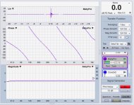
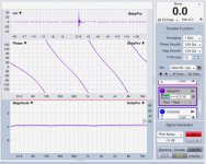
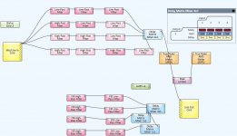
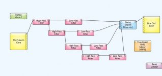
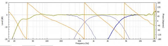
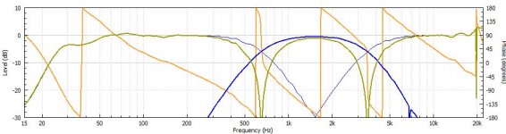
So I just finished building a DSP setup using the 'all-to-all' topology, and your crossover points. The 4 channels are then summed via a mixer, and i ran measurements on the summed response.
I did the same thing for the cascade arrangement.
Both transfers are shown below....as you can see, all-to-all (first one) is a bit smoother.
I also included screen grabs of the dsp platform (q-sys) that makes these setups and measurements so easy, and as evidence that they are real
If you're into this stuff...my strongest recommendation would be to check out FIR and linear phase crossovers...makes using IIR smell like walking thru poo...
I too spend a lot of time studying active xovers because I think it is essential to understand them separately before considering the summed acoustical output with a driver.
Which means I also agree very much with your approach to shape the response of each driver before putting any crossovers in place.
This is essential to a stellar design, and makes it damn easy too
.I've found if I spend the requisite time flattening drivers' magnitude and phase both in-band and out-of-band as wide as reasonably possible,
I can then pretty much choose what acoustic response i want via crossover point/type selection.
I should disclose I predominantly use linear phase crossovers which makes this process incredibly simple compared to IIR crossovers.
But I do sometimes need to use IIR for live sound applications, where I have to keep latency to near nothing, so I study IIR too.
I had already looked at the LR cascading technique vs simple parallel crossovers, but had not seen the technique you and Davey showed.
So I just finished building a DSP setup using the 'all-to-all' topology, and your crossover points. The 4 channels are then summed via a mixer, and i ran measurements on the summed response.
I did the same thing for the cascade arrangement.
Both transfers are shown below....as you can see, all-to-all (first one) is a bit smoother.
I also included screen grabs of the dsp platform (q-sys) that makes these setups and measurements so easy, and as evidence that they are real
If you're into this stuff...my strongest recommendation would be to check out FIR and linear phase crossovers...makes using IIR smell like walking thru poo...
Attachments
Last edited:
No, its not a "core matter". It matters no more and no less than other "phase modifiers" in the reproduction chain. That was my point. The filters are simply passing their outputs to the drivers, which further modify the response before spitting out the signal from their acoustic center as sound, and then the propagation through the air further modifies the phase (and amplitude) of that sound.
Let me as you this: do you listen to the electrical signal or the acoustic one?
I am quite familiar with the subject matter and I fully agree that the actual acoustic response is what matters in the end.
The exercise of using Dirac pulses instead of actual loudspeaker impulse responses allows one to investigate how the crossover itself contributes to the result. There is not much hope for ending up with a good final response if one is not even able to make a crossover sum flat given perfect drivers*.
You've got to walk before you can run.
* No, I don't mean that the electrical response of an actual loudspeaker crossover design should sum flat
Some people never seem to get the scientific approach to this.
The driver's natural response is completetly irrelevant for the topic, as is the electrical XO function that results in the end. All that matters is the target function for the acoustic output. The electrical response is obtained by the quotient of the target and driver responses.
As I've said before, if you don't know about how to setup proper target functions you're not a *systematic* crossover desginer. Your don't know what your actual goal is and have no chance to use CAE tools with optimizers (as any optimizer needs a target).
It's not pointless, it's called scientific approach. This is what he has in common with people like Malcolm Hawksford, John Kreskovsky, Steen Duelund, ....It really bothered me that SL made such a big deal about the cascade arrangement of filters on his web site. His analysis seemed rather pointless, because...
HE DID NOT INCLUDE THE DRIVER RESPONSES!
Some people never seem to get the scientific approach to this.
The driver's natural response is completetly irrelevant for the topic, as is the electrical XO function that results in the end. All that matters is the target function for the acoustic output. The electrical response is obtained by the quotient of the target and driver responses.
As I've said before, if you don't know about how to setup proper target functions you're not a *systematic* crossover desginer. Your don't know what your actual goal is and have no chance to use CAE tools with optimizers (as any optimizer needs a target).
Um, how does:
not invalidate this:The driver's natural response is completetly irrelevant for the topic
How can you derive a quotient if you do not have the "irrelevant" driver response? You can't, therefore it is VERY relevant.All that matters is the target function for the acoustic output. The electrical response is obtained by the quotient of the target and driver responses
You just supported my argument that you must know, by measurement, the driver responses in order to form an accurate model of the loudspeaker. Thanks for your support!
I'm not sure what you mean, all subject to the same phase shift through the audio band?The goal is to have all the drivers operating in phase, which means that all the drivers must be subject to the same phase response through the filter (again, assuming otherwise perfectly flat driver responses).
Regarding "scientific approach"...
If the filters (the crossover) were independent of the drivers for any and all loudspeakers, yes, breaking down the problem into parts and solving one (the filters) so that you did not have to:
But that is not the case for loudspeakers. The goal is what remains the same, that is more or less flat frequency response, and integration of driver acoustic responses with roughly in-phase behavior in the crossover region between each band. With every change to drivers and cabinet, the driver responses change and as a result the filters must change too.
So, yes, you must go back and develop the crossover filters over and over again for each loudspeaker project. I do not mean you just change the crossover frequencies. The filter orders, Qs, etc. may be completely different. The more similar drivers and cabinet are to some previous project the more similar the filters will be as well.
If the filters (the crossover) were independent of the drivers for any and all loudspeakers, yes, breaking down the problem into parts and solving one (the filters) so that you did not have to:
would be the right "scientific" approach.develop the science underlying any device over and ver again redundantly
But that is not the case for loudspeakers. The goal is what remains the same, that is more or less flat frequency response, and integration of driver acoustic responses with roughly in-phase behavior in the crossover region between each band. With every change to drivers and cabinet, the driver responses change and as a result the filters must change too.
So, yes, you must go back and develop the crossover filters over and over again for each loudspeaker project. I do not mean you just change the crossover frequencies. The filter orders, Qs, etc. may be completely different. The more similar drivers and cabinet are to some previous project the more similar the filters will be as well.
To be more clear, I left the driver response out of the equation in the example because Linkwitz also did this, just to show the effect of the theory as clear as possible.
Then it's my job to get the driver responses as close as humanly possible to the target filter curves. How closer they are, the better the result.
When I have a go at this, I take the route of equalizing the drivers as close to flat as possible, and then applying the filter curve. The end result should be very close to the theory. How close you can get will determine the limitations of the equalizers and of the drivers themselves of coarse.
To help with a quick sim using real world system.
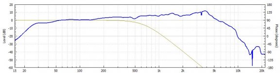
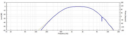
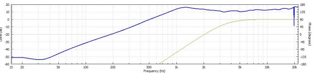
Here is a 3-way system with Scan 22W8534 bass, Scan 10F4424 mid, and SB26STCN tweeter. Widely known as a "Classic 3-way" concept so probably most are familiar with the shape and drivers' layout.
Attached is a simulation, using actual measurements taken during development (I am running it passive, with LR2 x/overs).
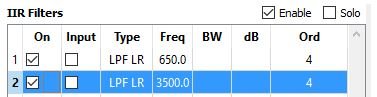
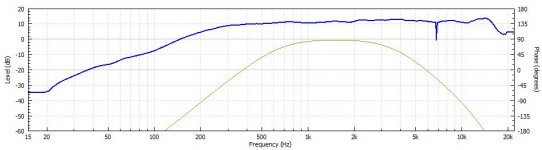
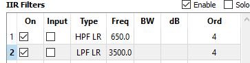
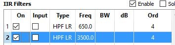
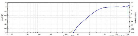
For this simulation the targets set were LR4 @ 650 and 3K5.
Used cascaded LR4 filters. The drivers were EQ-ed flat. The end FR is flat as expected. The system' phase rotations are @ 640 and 4K5.
Attached: Bass, Mid an Tweeter (raw FR, filters used+EQ+level trim) and the total system FR and phase output, in phase and with Mid reversed.
Here is a 3-way system with Scan 22W8534 bass, Scan 10F4424 mid, and SB26STCN tweeter. Widely known as a "Classic 3-way" concept so probably most are familiar with the shape and drivers' layout.
Attached is a simulation, using actual measurements taken during development (I am running it passive, with LR2 x/overs).
For this simulation the targets set were LR4 @ 650 and 3K5.
Used cascaded LR4 filters. The drivers were EQ-ed flat. The end FR is flat as expected. The system' phase rotations are @ 640 and 4K5.
Attached: Bass, Mid an Tweeter (raw FR, filters used+EQ+level trim) and the total system FR and phase output, in phase and with Mid reversed.
Attachments
-
 Bass raw.JPG48.4 KB · Views: 204
 -
 Bass filters.JPG16.9 KB · Views: 204
 -
 Mid raw.JPG49.3 KB · Views: 195
 -
 Mid filters.JPG16.1 KB · Views: 201
 -
 Mid filters, EQ, level.JPG45.4 KB · Views: 202
 -
 Tweeter raw.JPG51.6 KB · Views: 68
 -
 Tweeter filters.JPG16.8 KB · Views: 67
 -
 Tweeter filters, EQ, levels.JPG44.1 KB · Views: 61
 -
 Total system FR and phase.JPG49.8 KB · Views: 77
 -
 Total system - Mid reversed phase.JPG53.5 KB · Views: 87
Last edited:
To be more clear, I left the driver response out of the equation in the example because Linkwitz also did this, just to show the effect of the theory as clear as possible.
Then it's my job to get the driver responses as close as humanly possible to the target filter curves. How closer they are, the better the result.
When I have a go at this, I take the route of equalizing the drivers as close to flat as possible, and then applying the filter curve. The end result should be very close to the theory. How close you can get will determine the limitations of the equalizers and of the drivers themselves of coarse.
This approach with the LT is not so different than what SL used sometimes. By "EQ to flat" I assume you mean lift the driver response both above and below its passband, plus some EQ to smooth out peaks and dips within the passband. For a transducer that has infinite bandwidth (DC to infinity) the minimum phase response will be a flat as well. This is in theory a solution.
The low end of a driver's response can be lifted with an LT in this way because it nominally follows a second order (assuming closed box) response. The combination of the LT and the driver are then considered together as a new "driver" with a response that can be extended far towards being flat to DC.
At the upper end of a driver's natural response you have a much more complicated source that is becoming chaotic (in a sense) in the breakup region. Trying to come up with filters that will flatten this response to infinitely high frequency is not really feasible. The consequence is that when you use the transducer near its upper bound (within a couple octaves of the ultimate rolloff) the phase in the passband will be influenced by this rolloff.
By using multiple bands, and in each band using a "small" driver that is operating near the resonance end of its passband, and by using the LT on each to eliminate the phase rotation from the low end of each driver's passband, you can probably be successful with your filters without regard for what the driver is doing. Since the distortion is typically rising around a driver's resonance and the LT will not change this, it is better to use a driver away from its resonance - in the middle part of the passband. Also, the crossover will include the new filters based on the driver responses, so in one sense it's no longer what you proposed in your original post. Similarly, when you say that you will "get the driver responses as close as humanly possible to the target filter curves" that is also modifying the crossover by adding more filters or changing the ones you have developed.
One motivation for my critique of your post was my feat that a less informed DIYer will read the thread, take a look at the nice bands summing together in your CAD model of the filters, and say "That's the crossover that I should use!" without knowing about all these other details that might make it less than ideal as the actual loudspeaker crossover. I wish that SL has also made that more clear in his original web posts about the subject or added the caveat that it would work best when responses were corrected to be as wide band (e.g. flat both down as close to DC and as high in frequency) as possible. One way or the other, the DIYer must know the driver responses in order to come up with a good crossover.
From the DSP standpoint it is easy to look at the crossover in terms of standard filter functions (your OP for example) plus more filters to compensate for the drivers, cabinet, and so on. That is certainly valid, however, I think this is where DIYers can and should adapt the approach of passive crossover designers. They do not take an off-the-shelf passive crossover and then add on more components to fit to the drivers in the loudspeaker. Instead they modify components within a few basic circuit topologies to tailor the filter+driver responses to some target. This approach works with most drivers, and they call the others "difficult to work with". With active crossovers this would mean completely changing the filters from "standard" ones to compensate for the driver responses and adding EQ when necessary. This may mean adding or removing filter stages, changing Q, using asymmetric slopes, and so on. In the end you will no longer have textbook filters and this is why I do not advocate developing them to a high degree a priori.
That should certainly help discrimination in a blind testIf you're into this stuff...my strongest recommendation would be to check out FIR and linear phase crossovers...makes using IIR smell like walking thru poo...
From the DSP standpoint it is easy to look at the crossover in terms of standard filter functions (your OP for example) plus more filters to compensate for the drivers, cabinet, and so on. That is certainly valid, however, I think this is where DIYers can and should adapt the approach of passive crossover designers.
Lot's of good points in the previous (snipped) parts of your post. Thx.
If I may just focus on the quote above.....
Because I think the approach to adapt that of the passive crossover when using DSP, is to suffer the same co-mingling of driver correction and crossover selection that has historically made system design so arcane.
IME, it is much easier and gives better results to use DSP to address items individually, ....driver compensation, crossovers, timings, levels, etc.
Step at a time, in logical order....with DSP there is no need to juggle multiple tuning tasks together anymore..that's what I'd like the new DIYers to realize...it's not nearly as hard as we so often make it....
Maybe I missed something here (?), but was not the inclusion of phase correcting all-pass filters part of Linkwitz's original filter specification? Certainly analogue active crossovers of any merit over the last 30 years have included all-pass elements to achieve the very goal set out at the start of this thread.
One useful nugget is that each Linkwitz-Riley second order element can be compensated by a straightforward first order all-pass section. You just need as many as required to achieve the desired phase compensation in the "non-filtered" channels. Linkwitz's AES paper also makes known the use of all-pass filters to compensate for the lobing due to driver displacements.
And something that separates passive crossover design from DSP implementations is having to manage the driver impedances in the design process. It provides a significant design consideration that is not part of the DSP design process - and often ignored in passive speakers too!
It's not relevant for crossover theory, this is what I meant to say. It of course *is* relevant for the implementation of a given speaker... for which it is a good idea to have a precisly known and well understood theoretical model, isn't it?How can you derive a quotient if you do not have the "irrelevant" driver response? You can't, therefore it is VERY relevant.
Yes, this is entirely true. Typically you cannot re-use any exisiting electrical crossover for a different project even when the acustical targets are the same. But synthesizing the actual electric crossover is just the final step most of which can be automated, it always follows the same processing steps. A skilled person with a tool like LSPcad can make a crossover (full electrical circuit) for a 3-way active speaker within an hour or so (after proper measurements are availabe), once you have your tool chain set up and using some educated guesses :So, yes, you must go back and develop the crossover filters over and over again for each loudspeaker project. I do not mean you just change the crossover frequencies. The filter orders, Qs, etc. may be completely different. The more similar drivers and cabinet are to some previous project the more similar the filters will be as well.
- determine required electrical transfer function to arrive at the target by division of acoustical target by driver raw response.
- synthesize a chain of parametric building blocks (HP/LP/Peak/Dip/Shelve/Allpass/Delay) that match the needed electrical transfer, using optimizer to speed up the iterative process by varying the parameters.
- realize the actual circuits needed to implement the parametric blocks, again using optimizer, this time to arrive at component values.
Of course, for a one-off DIY project the situation is different but once you start getting into this and start to design several speakers the systematic approach pays off big time. And if this is your day job, even more so.
Last edited:
I aggree that nomally you would duplicate the phase terms with allpass sections, but most often a better implemetation is using high- and lowpasses and take their additional filtering effect for free. Normally, the amplitude irregularity penalty is minimal (narrow-band -1dB max dip or so). The perfect phase matching is the far more important goal as this makes for the coherent sound of this type of speakersMaybe I missed something here (?), but was not the inclusion of phase correcting all-pass filters part of Linkwitz's original filter specification? Certainly analogue active crossovers of any merit over the last 30 years have included all-pass elements to achieve the very goal set out at the start of this thread.
One useful nugget is that each Linkwitz-Riley second order element can be compensated by a straightforward first order all-pass section. You just need as many as required to achieve the desired phase compensation in the "non-filtered" channels. Linkwitz's AES paper also makes known the use of all-pass filters to compensate for the lobing due to driver displacements.
Last edited:
I'm not sure what you mean, all subject to the same phase shift through the audio band?
I'll try one more timeThe perfect phase matching is the far more importand goal as this makes for the coherent sound of this type of speakers
Are some people talking about phase matched across all the drivers at all frequencies?Yes, this is the goal and can be perfectly achieved (I'll post an example later -- 2.5-way with delay compensation for a slighty forward tweeter, curently I'm on a Linux machine, need to install WINE and LSPcad on this first). Of course inter-driver phase is not relevant anymore once the targeted response of a driver is down some 30dB or so.I'll try one more time
- Status
- This old topic is closed. If you want to reopen this topic, contact a moderator using the "Report Post" button.
- Home
- Loudspeakers
- Multi-Way
- A little addition to multiway crossovers a la Linkwitz: multi-cascading