Objective:
1. Pattern Control down to about 400 Hz or below
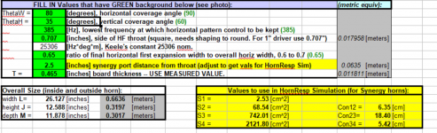
2. Needs to be able to fit within about (28W x12.5H x 17D) inches - the internal dimensions of the top section of my klipsch belle inspired clone.
3. Intend to use a pair Klipsch Belle Bass Bins below 400 Hz
4. I picked the GRS 5SBM-8 ( GRS 5SBM-8 5" Sealed Back Midrange ) intending to use a quad of them
5. Highs will be either PRV Audio D290Py-B (PRV Audio D290Py-B 1" Polyimide Horn Compression Driver 8 Ohm 2/3-Bolt) or Tymphany DFM-2535R00-08 ( Peerless by Tymphany DFM-2535R00-08 1" Compression Horn Driver 2/4-Bolt 8 Ohm ) or even the Dayton D250P which I own (and happen to like) ( Dayton Audio D250P-8 1" Polyimide Compression Horn Driver )
6. Intended crossover freq based on 1/4WL of tap length (2.5") = 1346 Hz
a. Need to see if this is physically possible
b. Do I need to account for distance from compression driver diaphragm to horn throat - effectively reducing the tap length by the same amount (or reducing the max crossover frequency accordingly?)
Any thoughts / criticisms welcome .
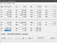
FWW, I pulled the T/S params off another post as I don't yet have hte GRS mids to measure.
Also, can someone explain why what relevance Vt and Atc have for MEH / Synergy horns. I thought all I would have needed to pay attention to were Ap1 and Lp.
Lastly, I'm a bit confused by the rule of thumb mentioned here - I think I satisy it but am not sure if I'm optimal or not .
https://www.diyaudio.com/forums/mul...e-bandpass-mid-unity-horn-29.html#post2668437
"
We now look at what the cross sectional area of our horn is at a distance of 5.7 cm. Let’s say the area is 41.5 cm^2. The circumference inside the horn at this point is 22.8 cm. Which is the WL of 1.5KHz. The thing I have found is if you set up your horn like this, you will end up with a bump, or a suck out at 1.5KHz. What you really need to do is leave a narrow gap between the mids and compression driver so the acoustic summation will result in a flat frequency response.
"
1. Pattern Control down to about 400 Hz or below
2. Needs to be able to fit within about (28W x12.5H x 17D) inches - the internal dimensions of the top section of my klipsch belle inspired clone.
3. Intend to use a pair Klipsch Belle Bass Bins below 400 Hz
4. I picked the GRS 5SBM-8 ( GRS 5SBM-8 5" Sealed Back Midrange ) intending to use a quad of them
5. Highs will be either PRV Audio D290Py-B (PRV Audio D290Py-B 1" Polyimide Horn Compression Driver 8 Ohm 2/3-Bolt) or Tymphany DFM-2535R00-08 ( Peerless by Tymphany DFM-2535R00-08 1" Compression Horn Driver 2/4-Bolt 8 Ohm ) or even the Dayton D250P which I own (and happen to like) ( Dayton Audio D250P-8 1" Polyimide Compression Horn Driver )
6. Intended crossover freq based on 1/4WL of tap length (2.5") = 1346 Hz
a. Need to see if this is physically possible
b. Do I need to account for distance from compression driver diaphragm to horn throat - effectively reducing the tap length by the same amount (or reducing the max crossover frequency accordingly?)
Any thoughts / criticisms welcome .
FWW, I pulled the T/S params off another post as I don't yet have hte GRS mids to measure.
Also, can someone explain why what relevance Vt and Atc have for MEH / Synergy horns. I thought all I would have needed to pay attention to were Ap1 and Lp.
Lastly, I'm a bit confused by the rule of thumb mentioned here - I think I satisy it but am not sure if I'm optimal or not .
https://www.diyaudio.com/forums/mul...e-bandpass-mid-unity-horn-29.html#post2668437
"
We now look at what the cross sectional area of our horn is at a distance of 5.7 cm. Let’s say the area is 41.5 cm^2. The circumference inside the horn at this point is 22.8 cm. Which is the WL of 1.5KHz. The thing I have found is if you set up your horn like this, you will end up with a bump, or a suck out at 1.5KHz. What you really need to do is leave a narrow gap between the mids and compression driver so the acoustic summation will result in a flat frequency response.
"
Attachments
Any thoughts / criticisms welcome .
Suggest you use the Multiple Entry Horn model, rather than the OD option.
Suggest you use the Multiple Entry Horn model, rather than the OD option.
Thanks
I find the MEH model confusing to use . I'd be glad to write up a tutorial if you can spare some effort to clarify my questions on this thread
Hello Zobsky, I will paste some info I found regarding MEH on diyaudio. Maybe you will find answers (and more questions ") ) in this text. Here it goes:
) in this text. Here it goes:
If you can't get a 3" mid to go higher than 900hz on a Synergy horn it's time to find a new midrange IMO.
This is not the case. In every case I've found the tap in point to be the reason why the mids drop off too early.
Even piece of crap Curtis Mathes mids can work well into the 2KHz to 3KHz range.
http://www.goodsoundclub.com/PDF/Synergy_Patent.pdf
__________________
Most people are using flare rate and cutoff frequency interchangeably. A driver tapped into a Synergy style speaker will not play LOWER in
frequency than the local flare rate/cutoff frequency. A driver tapped into a Synergy style speaker will normally play up to a frequency where
the circumference of the cross sectional area of the tap is equal to one wavelength.
Example: You have a mid tap into the horn where the area is 60cm^2. To find the local flare rate/cutoff frequency you use Horn Response to
calculate the length it takes for it to reach 120cm^2 (a doubling of area). Lets say it takes 4cm to go from 60cm^2 to 120cm^2 in our conical
horn. Highlight the horn segment in Horn Response and press the E key on your keyboard to change the horn profile from conical to exponential.
The flare rate will now be displayed. In this example it should tell you the flare rate is 474.37Hz. This is how low you can expect the mids to play
provided there are not issues with your horn build. Now to figure out how high it will play. We can calculate what the circumference of a circle
with an area of 60cm^2. It is 27.45cm long. a 1248Hz sound wave is 27.48cm long. Therefore we can expect our mid to play reasonably well
between about 470Hz - 1250Hz. One last detail is the cancellation notch. If you space the mids too far down the horn, the notch will over ride
everything. If the notch occurs at 1000Hz, than that is highest you will get out of the mid.
__________________
I'll go over this one last time. To reach your desired high frequency output of the mids the following must be true:
1.) The circumference of the cross sectional area must be equal to or less than 1 wave length of the highest frequency.
2.) The distance between the acoustical center of the compression driver and the tap point must be one half a wave length or less.
In most cases people are getting the mids close (satisfying number 2), but fail to ensure the area is correct.
Everyone needs to re-read the Synergy horn patent again.
*********************************************
The ideal balance is when the circumference of the area the mids tap into is equal to one wave length of the highest frequency, and the
distance between the acoustical center of compression driver and mids is half a wave length of the highest frequency. In your case of 1.5KHz
this would mean that you want to tap the mids into the horn with an area of 41.65cm^2 that is 11.42cm from the acoustical center of the
compression driver.
***********************************************
Let’s use an example where we are crossing over a compression driver at 1200Hz. At this frequency the full wave length is about 28.56cm long.
If we take this compression driver and load it into a conical horn, the horn will stop providing a load to the driver around where it expands to
64.91cm^2. Once you expand to beyond an area that is greater than one full wave length, the driver can no longer exert any pressure against
the horn walls. (The juvenile analogy I use is it becomes like throwing a hotdog down a hallway.) Now take this a step further and use a
square/rectangular horn instead of an axis symmetrical horn. The pressure in the corners drops even sooner than the flat side walls. Tuck your
entry ports in the corners, and there is almost zero chance of them interfering with the compression driver’s output. To fully ensure you won’t
get interference, you want to tap the mids in where the area is slightly larger than 64.91cm^2. We design to have a small gap between when
the compression driver unloads, and when the mids turn on. There will be enough summing at the crossover point to provide a flat power response.
There should not be a dip in response.
*******************************************
What I aim for is having the cancellation notch slightly lower in frequency than my crossover point for the mid. (e.g. Crossover is 1st order
lowpass at 1300Hz, notch at around 1200Hz to 1250Hz.) You want the acoustical cancellation notch doing most of the filtering work. If you
place your crossover point too close to the notch, you end up with a peak in response once it sums with the compression driver and its crossover.
The 1st order lowpass on the mid is there for phase shifting, and to filter out the mids high frequencies once it rebounds from the notch an
octave above.
*******************************************
But the flare rate itself is expressed in a reciprocal length (doubling of cross-sectional area). The cut off frequency and the flare rate are proportional:
100 Hz : 3,66 x 1/m = 0,0931 x 1/inch = 1.12" per foot
200 Hz : 7,33 x 1/m = 0,1861 x 1/inch = 2.32" per foot
300 Hz : 10,99 x 1/m = 0,2792 x 1/inch = 3.36" per foot
400 Hz : 4.48" per foot
A. To determine throat area: At = (2Pi)(Fs)(Qts)(Vas)/c
where At = throat area in sq. ft.; Fs = driver's resonance frequency in Hz;
Qts = driver's total Q factor; Vas = compliance as equivalent volume of air in cu. ft.
B. To determine mouth area: Am = [1/(SF)(4Pi)](c/Fc)(c/Fc)
where Am = mouth size in sq. ft.; SF = Size Factor (SF1 is free space--like hanging above a cornfield; SF2 is half space--on a floor; SF4 is quarter space--on a floor and next to a wall; and SF8 is 1/8th space--in a corner); c = speed of sound in feet per sec. (1130); Fc = desired cutoff frequency (-3 dB).
The horn length should be at least 1/4 wavelength--in practice, the distance from the throat to the calculated mouth size using the contour formula below.
C: To determine contour (flare rate or flare frequency): Ax is equal to At times e raised to the power of 2x divided by xo.
where Ax is the area of the expansion at distance x from the throat; xo is equal to 2/k where k = (4Pi)(Fc)/c, where Fc is the desired cutoff and c is the speed of sound; e = a constant (like Pi, or 3.1416....); e = 2.71828....
So, for an example, using a Pioneer 10-inch instrument loudspeaker, A25GC40-51-F-Q, with an Fs of 30 Hz, a Qts of 0.15, and a Vas of 5.08 cubic feet, and figuring an exponential horn with a cutoff of 50 Hz with a size factor of 8 and a cabinet width (internal) of 16 inches, we find a throat area of 24 square inches, a mouth area of 730.4 square inches, a length of 73.6 inches; the distance in which the cross-sectional area doubles is about 14.94 inches.
Calculate Flare FC
4 x Pi(3.1416) x Fc... divide the result by 13,200... take that answer and divide .7 by the answer to obtain the Fc.
To get 'in the ballpark', find one that either is a closed back unit that resonates at ~SQRT(200*1400) = ~529 Hz, or if open back, then ~529 = 2*Fs/Qes. How you get there doesn't matter if you're not trying to get max efficiency out of it with 'X' diameter x 'Y' long vents. IIRC, TD's prototype driver's published specs were ~2*250 Hz/0.99 = 505 Hz, so I wouldn't get too hung up on the apparent need for a low Qt just because it's a horn app.
DANLEY INPUT
Hi All
Bear, that is correct, it is the mutual radiation which the drivers share when closely coupled which raises the electroacoustic efficiency of the direct radiator and it is the increase in radiation resistance which causes a horn to have a higher efficiency. For multiple drivers to coherently drive a horn as one source, that spacing must also be recognized.
Dumptruck poses questions;
#1, yes the physical / acoustic spacing MUST be held (that ¼ wl spacing or less) in order for the sources to radiate spatially as one acoustic source. With a larger spacing than about 1/3 wl, then the sources radiate independently, the mutual coupling is gone and what you get, depends on the vector sum of the two sources.
As you move around the speaker, whenever the difference in path length is N X 1/2wl, one has a cancellation notch and null in the polar pattern. In commercial sound while unavoidable using multiple sources, an interference pattern is very bad because the lobes that point out in the wrong directions (not the listening area) excite room sound and the directivity (energy in the right direction compared to energy going everywhere else) directly relates to being able to understand random words etc (and preserving information related to the stereo image in the recording).
#2, in all “normal crossovers” like those with names, once past first order, the summed output has an “all pass” phase response. That is a flat amplitude but phase rotation equal to the number of orders times 90 degrees. This places the upper and lower crossover outputs at two different times (hf first, lf later) and this can be seen looking at the Group delay of any simple crossover. Most crossovers do this and is normal behavior.
For the Synergy horns, part of the design uses the inverse spacing of the low, mid and high sources, conceptually like an FIR filter where passively, the hf is delayed the most, the mids less and lf the least to offset the electrical part.
This will not work with any “named” crossovers even without the magnitude and phase of the individual frequency bands added in. In this case, with all the drivers directly coupled acoustically, like signals through a resistor network, one cannot get away with an error or on gets a whopping big cancellation notch everywhere not just one spot..
This then requires a crossover who’s magnitude and phase is what is required to mate the magnitude and phases of each range and this is never a normal test book shape but one that is adapted to the conditions. How i do that has evolved but is certainly based on careful measurements of the real thing.
The SH-50 referenced that I designed in 2005 will reproduce a square wave from near perfect to fair on an O-scope, from about 250Hz to about 2900 Hz, spanning both crossovers and like most all of them, even the largest 10 feet tall with over 100 drivers, sounds like, acts like, measures like a single crossover-less driver.
The hf driver (BMS 4550) is already one of the top couple most efficient drivers available at any price. It is the wide dispersion, maintained up high, which forces it down. On a horn which narrowed up high, that driver can deliver over 110dB on axis sensitivity.
Keep in mind, on a CD horn, it is usually the hf drivers sensitivity in the top octave that limits the overall sensitivity.
The holes are another part of the design. You may have noticed that as you drive loudspeakers harder and harder, they get “bright” and eventually harsh sounding. Harmonic distortion starts an octave above the real signal and extends upwards by 2,3,4,5 etc times the input frequency.
While that brightness may not be objectionable, the object here is to be a faithful reproducer and one thing that means the spectral balance should not change with level if possible.
The trapped air volume under the cone and the small holes, form an acoustical 2nd order low pass filter, like an electrical filter but in air. The object being that the harmonic distortion the drivers invariably produce, will be attenuated and not enter the horn. The effect does limit the bandwidth and that is the object of it. The idea is you DO NOT want sound the driver produces on it’s own (not part of the input signal) which is always above the electrical crossover and the short obstruction does not affect the horns radiation resistance.
) in this text. Here it goes:If you can't get a 3" mid to go higher than 900hz on a Synergy horn it's time to find a new midrange IMO.
This is not the case. In every case I've found the tap in point to be the reason why the mids drop off too early.
Even piece of crap Curtis Mathes mids can work well into the 2KHz to 3KHz range.
http://www.goodsoundclub.com/PDF/Synergy_Patent.pdf
__________________
Most people are using flare rate and cutoff frequency interchangeably. A driver tapped into a Synergy style speaker will not play LOWER in
frequency than the local flare rate/cutoff frequency. A driver tapped into a Synergy style speaker will normally play up to a frequency where
the circumference of the cross sectional area of the tap is equal to one wavelength.
Example: You have a mid tap into the horn where the area is 60cm^2. To find the local flare rate/cutoff frequency you use Horn Response to
calculate the length it takes for it to reach 120cm^2 (a doubling of area). Lets say it takes 4cm to go from 60cm^2 to 120cm^2 in our conical
horn. Highlight the horn segment in Horn Response and press the E key on your keyboard to change the horn profile from conical to exponential.
The flare rate will now be displayed. In this example it should tell you the flare rate is 474.37Hz. This is how low you can expect the mids to play
provided there are not issues with your horn build. Now to figure out how high it will play. We can calculate what the circumference of a circle
with an area of 60cm^2. It is 27.45cm long. a 1248Hz sound wave is 27.48cm long. Therefore we can expect our mid to play reasonably well
between about 470Hz - 1250Hz. One last detail is the cancellation notch. If you space the mids too far down the horn, the notch will over ride
everything. If the notch occurs at 1000Hz, than that is highest you will get out of the mid.
__________________
I'll go over this one last time. To reach your desired high frequency output of the mids the following must be true:
1.) The circumference of the cross sectional area must be equal to or less than 1 wave length of the highest frequency.
2.) The distance between the acoustical center of the compression driver and the tap point must be one half a wave length or less.
In most cases people are getting the mids close (satisfying number 2), but fail to ensure the area is correct.
Everyone needs to re-read the Synergy horn patent again.
*********************************************
The ideal balance is when the circumference of the area the mids tap into is equal to one wave length of the highest frequency, and the
distance between the acoustical center of compression driver and mids is half a wave length of the highest frequency. In your case of 1.5KHz
this would mean that you want to tap the mids into the horn with an area of 41.65cm^2 that is 11.42cm from the acoustical center of the
compression driver.
***********************************************
Let’s use an example where we are crossing over a compression driver at 1200Hz. At this frequency the full wave length is about 28.56cm long.
If we take this compression driver and load it into a conical horn, the horn will stop providing a load to the driver around where it expands to
64.91cm^2. Once you expand to beyond an area that is greater than one full wave length, the driver can no longer exert any pressure against
the horn walls. (The juvenile analogy I use is it becomes like throwing a hotdog down a hallway.) Now take this a step further and use a
square/rectangular horn instead of an axis symmetrical horn. The pressure in the corners drops even sooner than the flat side walls. Tuck your
entry ports in the corners, and there is almost zero chance of them interfering with the compression driver’s output. To fully ensure you won’t
get interference, you want to tap the mids in where the area is slightly larger than 64.91cm^2. We design to have a small gap between when
the compression driver unloads, and when the mids turn on. There will be enough summing at the crossover point to provide a flat power response.
There should not be a dip in response.
*******************************************
What I aim for is having the cancellation notch slightly lower in frequency than my crossover point for the mid. (e.g. Crossover is 1st order
lowpass at 1300Hz, notch at around 1200Hz to 1250Hz.) You want the acoustical cancellation notch doing most of the filtering work. If you
place your crossover point too close to the notch, you end up with a peak in response once it sums with the compression driver and its crossover.
The 1st order lowpass on the mid is there for phase shifting, and to filter out the mids high frequencies once it rebounds from the notch an
octave above.
*******************************************
But the flare rate itself is expressed in a reciprocal length (doubling of cross-sectional area). The cut off frequency and the flare rate are proportional:
100 Hz : 3,66 x 1/m = 0,0931 x 1/inch = 1.12" per foot
200 Hz : 7,33 x 1/m = 0,1861 x 1/inch = 2.32" per foot
300 Hz : 10,99 x 1/m = 0,2792 x 1/inch = 3.36" per foot
400 Hz : 4.48" per foot
A. To determine throat area: At = (2Pi)(Fs)(Qts)(Vas)/c
where At = throat area in sq. ft.; Fs = driver's resonance frequency in Hz;
Qts = driver's total Q factor; Vas = compliance as equivalent volume of air in cu. ft.
B. To determine mouth area: Am = [1/(SF)(4Pi)](c/Fc)(c/Fc)
where Am = mouth size in sq. ft.; SF = Size Factor (SF1 is free space--like hanging above a cornfield; SF2 is half space--on a floor; SF4 is quarter space--on a floor and next to a wall; and SF8 is 1/8th space--in a corner); c = speed of sound in feet per sec. (1130); Fc = desired cutoff frequency (-3 dB).
The horn length should be at least 1/4 wavelength--in practice, the distance from the throat to the calculated mouth size using the contour formula below.
C: To determine contour (flare rate or flare frequency): Ax is equal to At times e raised to the power of 2x divided by xo.
where Ax is the area of the expansion at distance x from the throat; xo is equal to 2/k where k = (4Pi)(Fc)/c, where Fc is the desired cutoff and c is the speed of sound; e = a constant (like Pi, or 3.1416....); e = 2.71828....
So, for an example, using a Pioneer 10-inch instrument loudspeaker, A25GC40-51-F-Q, with an Fs of 30 Hz, a Qts of 0.15, and a Vas of 5.08 cubic feet, and figuring an exponential horn with a cutoff of 50 Hz with a size factor of 8 and a cabinet width (internal) of 16 inches, we find a throat area of 24 square inches, a mouth area of 730.4 square inches, a length of 73.6 inches; the distance in which the cross-sectional area doubles is about 14.94 inches.
Calculate Flare FC
4 x Pi(3.1416) x Fc... divide the result by 13,200... take that answer and divide .7 by the answer to obtain the Fc.
To get 'in the ballpark', find one that either is a closed back unit that resonates at ~SQRT(200*1400) = ~529 Hz, or if open back, then ~529 = 2*Fs/Qes. How you get there doesn't matter if you're not trying to get max efficiency out of it with 'X' diameter x 'Y' long vents. IIRC, TD's prototype driver's published specs were ~2*250 Hz/0.99 = 505 Hz, so I wouldn't get too hung up on the apparent need for a low Qt just because it's a horn app.
DANLEY INPUT
Hi All
Bear, that is correct, it is the mutual radiation which the drivers share when closely coupled which raises the electroacoustic efficiency of the direct radiator and it is the increase in radiation resistance which causes a horn to have a higher efficiency. For multiple drivers to coherently drive a horn as one source, that spacing must also be recognized.
Dumptruck poses questions;
#1, yes the physical / acoustic spacing MUST be held (that ¼ wl spacing or less) in order for the sources to radiate spatially as one acoustic source. With a larger spacing than about 1/3 wl, then the sources radiate independently, the mutual coupling is gone and what you get, depends on the vector sum of the two sources.
As you move around the speaker, whenever the difference in path length is N X 1/2wl, one has a cancellation notch and null in the polar pattern. In commercial sound while unavoidable using multiple sources, an interference pattern is very bad because the lobes that point out in the wrong directions (not the listening area) excite room sound and the directivity (energy in the right direction compared to energy going everywhere else) directly relates to being able to understand random words etc (and preserving information related to the stereo image in the recording).
#2, in all “normal crossovers” like those with names, once past first order, the summed output has an “all pass” phase response. That is a flat amplitude but phase rotation equal to the number of orders times 90 degrees. This places the upper and lower crossover outputs at two different times (hf first, lf later) and this can be seen looking at the Group delay of any simple crossover. Most crossovers do this and is normal behavior.
For the Synergy horns, part of the design uses the inverse spacing of the low, mid and high sources, conceptually like an FIR filter where passively, the hf is delayed the most, the mids less and lf the least to offset the electrical part.
This will not work with any “named” crossovers even without the magnitude and phase of the individual frequency bands added in. In this case, with all the drivers directly coupled acoustically, like signals through a resistor network, one cannot get away with an error or on gets a whopping big cancellation notch everywhere not just one spot..
This then requires a crossover who’s magnitude and phase is what is required to mate the magnitude and phases of each range and this is never a normal test book shape but one that is adapted to the conditions. How i do that has evolved but is certainly based on careful measurements of the real thing.
The SH-50 referenced that I designed in 2005 will reproduce a square wave from near perfect to fair on an O-scope, from about 250Hz to about 2900 Hz, spanning both crossovers and like most all of them, even the largest 10 feet tall with over 100 drivers, sounds like, acts like, measures like a single crossover-less driver.
The hf driver (BMS 4550) is already one of the top couple most efficient drivers available at any price. It is the wide dispersion, maintained up high, which forces it down. On a horn which narrowed up high, that driver can deliver over 110dB on axis sensitivity.
Keep in mind, on a CD horn, it is usually the hf drivers sensitivity in the top octave that limits the overall sensitivity.
The holes are another part of the design. You may have noticed that as you drive loudspeakers harder and harder, they get “bright” and eventually harsh sounding. Harmonic distortion starts an octave above the real signal and extends upwards by 2,3,4,5 etc times the input frequency.
While that brightness may not be objectionable, the object here is to be a faithful reproducer and one thing that means the spectral balance should not change with level if possible.
The trapped air volume under the cone and the small holes, form an acoustical 2nd order low pass filter, like an electrical filter but in air. The object being that the harmonic distortion the drivers invariably produce, will be attenuated and not enter the horn. The effect does limit the bandwidth and that is the object of it. The idea is you DO NOT want sound the driver produces on it’s own (not part of the input signal) which is always above the electrical crossover and the short obstruction does not affect the horns radiation resistance.
re' Also, can someone explain why what relevance Vt and Atc have for MEH / Synergy ho
Vtc and Atc affect the steepness of the acoustic low pass filter that is formed by the bandpass chamber. Trapping too much air under the cone lowers the cutoff frequency. They also interact with the port area and length. Play with all these parameters to optimize your mid's response.
Vtc and Atc affect the steepness of the acoustic low pass filter that is formed by the bandpass chamber. Trapping too much air under the cone lowers the cutoff frequency. They also interact with the port area and length. Play with all these parameters to optimize your mid's response.
I find the MEH model confusing to use . I'd be glad to write up a tutorial if you can spare some effort to clarify my questions on this thread
If you require any clarification on how to use the MEH functionality in Hornresp, I would be only too happy to oblige.
As a starting point, try reading the Multiple Entry Horn Wizard section in the Help file, and then create an example design using the Input Wizard, accessed from the Help menu.
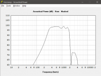
I believe that you've overconstrained your requirements already. Which one is it? That size mouth is too small in the vertical direction to control the pattern down to 400 Hz. It's going to lose vertical pattern control at about 600 Hz or higher, depending on the actual height of the horn mouth with flanges (which are assumed to be there taking up real estate). Recommend increasing the vertical dimension to at least 17 inches high, and the width to be ~27 inches in order to achieve 90 x 60 degrees pattern coverage down to 400 Hz, i.e., without pattern flip or other issues from having a horn that is too different in vertical vs. horizontal pattern ratio. You really don't want to cross higher than ~400 Hz in order to avoid the extremely narrow polars of the "W" shape horn-loaded bass bin.Objective:
1. Pattern Control down to about 400 Hz or below
2. Needs to be able to fit within about (28W x12.5H x 17D) inches - the internal dimensions of the top section of my klipsch belle inspired clone.
Objective:
...6. Intended crossover freq based on 1/4WL of tap length (2.5") = 1346 Hz
a. Need to see if this is physically possible
b. Do I need to account for distance from compression driver diaphragm to horn throat - effectively reducing the tap length by the same amount (or reducing the max crossover frequency accordingly?)
I know that you've titled the thread "multiple-entry horn", but why cross there? That's way too low. And it's also way too hard to get everything stuffed into the box and mounted on the back side of the horn. This will also lead to coverage and phase anomalies near the midrange-woofer crossover frequency--not to mention the absolutely atrocious time trying to get a passive crossover designed that will do a proper job--including passive notch filters to flatten the overall response. (Trust me on this point.)
Why not build a 1.4", 1.5" or 2" throat horn and use a BMS dual-diaphragm driver instead--crossing at 6.5 kHz? Or you could use a single diaphragm driver instead (of higher quality) and do it in two steps (i.e., a fully horn loaded two-way). A (passive) crossover to put everything together would be a walk in the park by comparison. The overall cost would actually be lower once you get a passive crossover finally dialed in with notch filters, etc.
In answer to your last quoted question, in my experience you need to measure the distance from the off-axis port penetration into the horn, and keep the volume of air behind the port to the diaphragm at an absolute minimum.
Again, this would favor a dual-diaphragm driver over an MEH configuration with off-axis ports. The off-axis ports would favor a full-range MEH (like a K-402-sized horn) and dual woofers which are positioned on the straight-sided horn to take advantage of the much better flare rate of the lower portion of the horn. Your bass response would be about an octave deeper than your Belle-like bins, and the overall size of the loudspeaker would be more like a La Scala or Belle volumetrically.
You could also look at using an ESS AMT-1 ($140 each) on top to cross below 2 kHz to a midrange driver/horn, and let the midrange handle the gap between the Belle-like bass bin performance and an 800-2000 Hz crossover point with the AMT-1. The phase and time-alignment issues would be greater than a dual-diaphragm compression driver, but the crossover design/implementation and resulting sound would be really good--a dipole ribbon HF sound.
You could also place off-axis ports for the midrange driver mounted to one side of the last fold of the bass bin itself, thus avoiding another horn mouth to feed.
JMTC.
Chris
Last edited:
By the way, I had a lot of trouble understanding how to use the multiple-entry-horn wizard in Hornresp, too: https://www.diyaudio.com/forums/subwoofers/119854-hornresp-554.html#post4364005
But when I finally figured out the secret handshake, it worked quite well. It's probably worth your time to make it work at least once.
Chris
But when I finally figured out the secret handshake, it worked quite well. It's probably worth your time to make it work at least once.
Chris
Last edited:
1. Pattern Control down to about 400 Hz or below
IMO Cask05 has a good point (post 7). Also see note below.
Conflicts with the above2. Needs to be able to fit within about (28W x12.5H x 17D) inches - the internal dimensions of the top section of my klipsch belle inspired clone.
4. I picked the GRS 5SBM-8 ( GRS 5SBM-8 5" Sealed Back Midrange ) intending to use a quad of them
5. Highs will be [...] the Dayton D250P which I own (and happen to like) ( Dayton Audio D250P-8 1" Polyimide Compression Horn Driver )
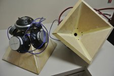
This driver configuration has been done before.
Suitable midrange cone, for bandpass mid in Unity horn.
See post 1658 (picture)
Note that you could improve the driver positioning. He placed the mids so they were centred on their horn walls. The flanges touched, which limited how close to the throat he could get them. If you offset each driver by ~2cm from the middle of each horn wall, you could pack yours slightly closer in.
You could also tighten it up by grinding / sawing some material off the flanges.
Posts 1654 and 2033 in that same thread are pertinent to your other questions.
6. Intended crossover freq based on 1/4WL of tap length (2.5") = 1346 Hz
FR plots from that earlier build (post 2033) indicate the mids would need 12dB of HF boost for a cross that high.
To me, that much response sculpting requires active eq. Or you could use a more robust HF driver to cross lower down. Or you could do both. I prefer both.
Agreed. My guesstimate is > 1kHz.It's going to lose vertical pattern control at about 600 Hz or higher, depending on the actual height of the horn mouth with flanges (which are assumed to be there taking up real estate).
I know that you've titled the thread "multiple-entry horn", but why cross there? That's way too low.
Confused - which thing do you think is too low?
NOTE (1)
A minor trick to simplify the construction (if using basic tools).
I recently built a basic Syn prototype with dimensions very close to what Cask05 recommends.
I picked 90 x 65.52 degrees (horizontal control to 400Hz, vertical to 750Hz).
Using these angles set the angles (z) and (r) in Synergy Calc to 45 degrees and 22.5 degrees. I own router bits with these angles - it makes for an easier build than going with 60 degrees vertical.
NOTE (2)
Another minor trick:
Don't make the whole horn from thick plywood. Make it from thin material, and maintain rigidity by laminating on extra layers for the mouth sections.
--> your midrange taps will be much shorter.
NOTE (3)
I have a few pairs of 1" drivers (JBL, Dayton, Tymphany) but am using a small fullrange driver instead cos it sounds nice and works with a low crossover. I'm using a Tymphany 2", but Fountek, SB and others are probably just as worthy.
NOTE (4)
I'm awful at complicated stuff like notch filters with passive crossovers. Multi amp systems work better.
If on a budget: could you make a very simple passive crossover, then add a layer of eq at the source (e.g. using Equaliser APO, which is free)?
Attachments
By the way, I had a lot of trouble understanding how to use the multiple-entry-horn wizard in Hornresp, too: https://www.diyaudio.com/forums/subwoofers/119854-hornresp-554.html#post4364005
But when I finally figured out the secret handshake, it worked quite well. It's probably worth your time to make it work at least once.
Chris
Thanks.
Looks like we're neighbors , relatively speaking . Do you mind if I reach out to you offline with any questions ?
BTW, I also own a pair of 1.4" exit fsital compression drivers in case crossing over lower makes more sense . I haven't seen folks ever usin 1.4" CD in a MEH, wonder why.
Give me a day or two to digest all the information and I'll try and respond with something sensible ��
Give me a day or two to digest all the information and I'll try and respond with something sensible ��
. I haven't seen folks ever usin 1.4" CD in a MEH, wonder why.
QUOTE]
SynTripP: 2-way 2-part Virtual Single Point Source Horn
Confused - which thing do you think is too low?
It's of course not really too low for a 1" compression driver of good quality to cover. But if you're going to do that, a 1.4" to 2" compression driver of either single or dual diaphragm type can eliminate the need for the cone midranges, the very close spacing of the midrange off-axis ports (which can lead to anomalies in coverage and frequency response near a 1-2 kHz crossover point), and the issues that I've seen with the crossover design to pull it all together with flat response and still have very good phase/group delay through the most sensitive frequency bands of the human hearing system. I'd rather get farther away from the throat of the horn with off-axis ports and leave the job of the HF crossover to the compression driver manufacturer (e.g., BMS dual diaphragm) or even eliminate it altogether using a single Be-diaphragm compression drivers of 1.4-2 inch size. The distortion is lower than 1" drivers. I also find that it's easier to control crossover amplitude/phase and combined directivity effects in the horn the farther the off-axis ports are located from the throat.
You can PM here or on the K-forum (user: Chris A).Do you mind if I reach out to you offline with any questions?
Chris
- Status
- This old topic is closed. If you want to reopen this topic, contact a moderator using the "Report Post" button.
- Home
- Loudspeakers
- Multi-Way
- Please Critique my multi-entry horn simulation