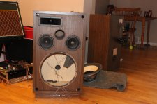
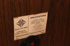
A customer brought me a pair of Telefunken TFK 6006 speakers needing repair. They are a 4 way design.
I discovered one of the two L-pads in each speaker is toasted. The reset switch doesn't seem to hot either. The L-pads are 50ohm, which seems to be unusual.
What are my options for replacement?
I discovered one of the two L-pads in each speaker is toasted. The reset switch doesn't seem to hot either. The L-pads are 50ohm, which seems to be unusual.
What are my options for replacement?
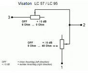
This is how Visaton l pads measure. Check your own and ask additional information at the stores.
I can't quite make sense of this diagram? It is showing two Lpads of different resistances? Or maybe each L-pad has a different resistance on each side of the center tap?
I suppose if I use a lower resistance L-pad I just won't be able to turn the mids down as much, right? (It is the mid level controls)
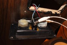
Maybe I'm not quite understanding what an Lpad is. Maybe these aren't actually Lpads. There are three terminals but only two are connected.
What I am sure of is whatever it is, it is very dead.
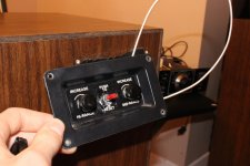
Here's a picture. (There were two wires connected to the open pot but one broke off)
What I am sure of is whatever it is, it is very dead.
Here's a picture. (There were two wires connected to the open pot but one broke off)
Attachments
![IMG_4556[1].jpg](/community/data/attachments/650/650420-78148d374f6c45142be7a52c9c9466cf.jpg)
Last edited:
I can't quite make sense of this diagram?
Visaton schematic shows that an L-pad is consisted of 2 variable resistors. The one between terminals 3(IN) and 2(out) can have a resistance from 8 ohms to 0, and the one between 2 and 1(common) can have any resistance from 0 to 40 and infinitely high. The knob turned completely to the left would have maesured like this: 8 ohm (from 3 to 2) and 0 (from 1 to 2). The more you turn to the right the lesser becomes the first value and the larger the second one thus making the drive unit louder.
Yours are not L-pads, they are variable resistors (rheostats).
Ceramic Casing 25W 50ohm Variable Resistor Wire Wound Rheostat: Amazon.co.uk: Business, Industry & Science
You need something like the above. Connect to middle (wiper) termnal and one outer terminal.
Ceramic Casing 25W 50ohm Variable Resistor Wire Wound Rheostat: Amazon.co.uk: Business, Industry & Science
You need something like the above. Connect to middle (wiper) termnal and one outer terminal.
You should replace the L-pads with normal voltage divider, it sounds a LOT better, these darn things eat a lot of details.
Try different combinations, R1+R2=~40 Ohm, usually R1 (serial) is a low value (probably 1-5,6 Ohm), the R2 (parallel to -) is in praxis the much less critical in value (22-39Ohm ca.).
Try different combinations, R1+R2=~40 Ohm, usually R1 (serial) is a low value (probably 1-5,6 Ohm), the R2 (parallel to -) is in praxis the much less critical in value (22-39Ohm ca.).
How old are these speakers?
It was common to use 50 ohm rheostats to control levels in vintage speakers.
This usually pre-dates the introduction of variable, constant impedance L-pads.
The photograph clearly shows that rheostats were used and not L-pads.
If you simply want to renovate these speakers to original spec, then use 50 ohm rheostats.
You should replace the L-pads with normal voltage divider, it sounds a LOT better, these darn things eat a lot of details.
Try different combinations, R1+R2=~40 Ohm, usually R1 (serial) is a low value (probably 1-5,6 Ohm), the R2 (parallel to -) is in praxis the much less critical in value (22-39Ohm ca.).
The customer doesn't want to spend too much on these, and I have to redo a bad refoam job too. So I think this is the way I'll go as it is also the cheapest way.
The customer doesn't want to spend too much on these, and I have to redo a bad refoam job too. So I think this is the way I'll go as it is also the cheapest way.
A voltage divider consists of two resistors. That's much cheaper than a new L-Pad of some quality and dimensions (wattage).
It is a shame a loudspeaker will lack such a useful function, as an Lpad is, or a rheostat for that matter.
In theory, yes. In praxis - no. You adjust it one time and then it plays that way for years.
A voltage divider consists of two resistors. That's much cheaper than a new L-Pad of some quality and dimensions (wattage).
But since it is a potentiometer with only two wires connected and not an actual L-pad, it is even simpler and I only need one resistor. And I can try it with no resistor for max level.
But since it is a potentiometer with only two wires connected and not an actual L-pad, it is even simpler and I only need one resistor. And I can try it with no resistor for max level.
That's correct and wrong at the same time. While that's the same behaviour like the original crossover showed, it's still a bad design since the crossover frequency is impedance dependent. That means with changing the resistor value you change at the same time the crossover frequency, drop off slope and response. It would be the same like with the l-pad but that's a design flaw of the original speaker aswell.
Here are some pictures. There isn't a crossover board inside, there are caps soldered in line with wires. I guess I should map it out on paper and see what is going on.
I tested the drivers individually in one of the speakers, seemed okay.
I tested the drivers individually in one of the speakers, seemed okay.
Attachments
So I bypassed the breakers and mid level pots with jumpers and hooked my ohm meter to the main input terminals. Each speaker reads about 1.2ohms and the nominal rating is 8ohm... That's seems not right?
No, that is in fact not right. I suspect you've shorted the wrong connections.
Here are some pictures. There isn't a crossover board inside, there are caps soldered in line with wires. I guess I should map it out on paper and see what is going on.
I tested the drivers individually in one of the speakers, seemed okay.
Well, you took the photo from the wrong side (photo 4), it would really help to see the connection side of the pads and the capacitor(s) and the soldering points of them and the wires. The woofers are definitely not the original ones btw.
The Harman Kardon receiver is very nice!
- Status
- This old topic is closed. If you want to reopen this topic, contact a moderator using the "Report Post" button.
- Home
- Loudspeakers
- Multi-Way
- Telefunken TFK6006 50ohm Lpads