I'm about to replace some barrier strips on my live Mid-high speakers with Neutricks and a 4-pole switch. (The switch bypasses one internal crossover)
I'm wondering how high I need to go in the switches amperage rating, to not worry about any losses. I assume I don't need much, but wanted to check and be sure.
The speakers take a max of 1100w @ 8 ohms.
-----------------------
And also, what gauge wire is enough, for internal runs less than one foot?
- Thanks.
I'm about to replace some barrier strips on my live Mid-high speakers
with Neutricks and a 4-pole switch. what gauge wire is enough
SpeakONs are rated for 50A, so there's your maximum needed switch rating.
They take up to #10 wire, so there's your maximum needed wire size.
Last edited:
Thanks. - but those aren't MY numbers! 
I'm looking for the minimum values I can safely use, for low cost, low weight, and low footprint. I doubt a 50a 4-pole switch even exists.
Neutricks have to handle the most powerful transfers possible, for any speaker made.
Again, my speakers, pertinent to this query, handle a maximum of 1,000w.
-----------
And I've never seen internal wiring anywhere near 10 gauge. That would not be fun to solder.
I'll probably use 16 gauge, but thought I'd check here first.
Last edited:
I use this one for switching passives in and out because it has 4 poles.
I also use it to handle 4000w to subs (I put a small DC voltage on subs when not in use)
Member Login
I also use it to handle 4000w to subs (I put a small DC voltage on subs when not in use)
Member Login
You easily can get away with using Carling 254–73 4 pole screw-terminal switches. 15 amp capacity, not overly expensive. Less than twenty bucks at Mouser. The wire is equally flexible: 16 gauge tinned stranded copper is best, tho' "naked stranded copper" (i.e. without tinning) is fine too. Personally, I'd also use crimp-on lugs on the wire, available at any hardware store.
To give some idea how much power is lost not going to 10 gauge, not getting a huge 50 amp million dollar switch… its all about Ω.
Note that those would be peak amps, not average ones. For sound material being blasted at the full capacity of the speakers and amplifier.
however, if again you look at the formula, and express it slightly differently:
You notice that the power "lost" is only related to the ratio of the speakers' impedance to the added switch-and-wire resistance of making your change. And that … in this example … is 0.05 ÷ 4 → 0.0125 or basically 1% of the power.
Acoustically 1% is 20 log10( 1 - 0.0125 ) → –0.1 dB.
Turns out that we cannot hear –0.1 dB power drop. At all. 1 dB, yes. 0.1 dB, no.
Just saying,
GoatGuy
To give some idea how much power is lost not going to 10 gauge, not getting a huge 50 amp million dollar switch… its all about Ω.
P = I² R
R ≈ 4 Ω
P ≈ 1200 watts … therefore
I = √( 1200 ÷ 4 )
I = 17 amps
R ≈ 4 Ω
P ≈ 1200 watts … therefore
I = √( 1200 ÷ 4 )
I = 17 amps
Note that those would be peak amps, not average ones. For sound material being blasted at the full capacity of the speakers and amplifier.
however, if again you look at the formula, and express it slightly differently:
P = I²( R1 + R2 ) where
R1 ≈ 4 Ω (speakers)
R2 ≈ 0.05 Ω (switch + imperfect added wiring)
R1 ≈ 4 Ω (speakers)
R2 ≈ 0.05 Ω (switch + imperfect added wiring)
You notice that the power "lost" is only related to the ratio of the speakers' impedance to the added switch-and-wire resistance of making your change. And that … in this example … is 0.05 ÷ 4 → 0.0125 or basically 1% of the power.
Acoustically 1% is 20 log10( 1 - 0.0125 ) → –0.1 dB.
Turns out that we cannot hear –0.1 dB power drop. At all. 1 dB, yes. 0.1 dB, no.
Just saying,
GoatGuy
Do you plan on doing the switch during loud or soft passages?
B.
Not while actually using the speakers. (of course.)
Good, switching large currents off with an inductive load will arc at the contacts and eventualy destroy them. The conectors you want are called speakon they come in 2 and 4 conductor types. Can handle large currents, no soldering and easy no mistake connecting. They are kind expensive and youll need a set ( male/ female ) for each speaker. Almost an industry standard for PA.
(I put a small DC voltage on subs when not in use)
Forgive the hijack, but why would you do such a thing?
Wolf
Forgive the hijack, but why would you do such a thing?
Wolf
Yes, to OP... pls forgive my hi jack response too...
Oh, and here's a link to the switch i posted earlier that didn't go through
4PDT Heavy Duty Toggle Switch
Wolf, I use 18" drivers in a horizontal mount. Several pro-sound guys warned me about cone/voice coil sag when horizontal, and i contacted BMS who also said it isn't recommended because sooner or later sag will occur.
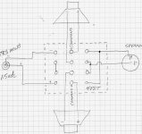
The small DC voltage lifts the cone/coil by the same amount that gravity pulls it down, so the DC keeps the coil centered when not in use, negating eventual sag.
Here's the circuit and the need for the switch..
Attachments
- Status
- This old topic is closed. If you want to reopen this topic, contact a moderator using the "Report Post" button.
- Home
- Loudspeakers
- Multi-Way
- Switches: What amperage? Wire: What gauge?