Need som advice on this crossover.
I built this speaker some 20 years ago. The crossover was designed by a local diy shop. I did not have any measuring equipment then.
I have now measured the speakers with omnimic, and modified the crossover using "boxsim" and trial and error.
See pictures
I have only change the values of the capacitors and resistors, not the coils. Because i did not have any other value coils.
My question: I might have achieved the same response by also changing the coils, but does it matter if i achieve the wanted response without changing coil values or a combination of both?? I did a simulation changing the 1.8mH coil to 1mH and it also simulated a relatively flat respons, with a big dip for "phase test"
Original filter

Measured with original filter

Modified filter

Measured with modified filter

Measured with modified filer and reversed tweeter polarity

Simulation

Does it matter what combination of component you use? I mean does one need to change both reactive and capacitive components in a 2nd order filter?
I do think the speakers sound very good now after the filter modification
I built this speaker some 20 years ago. The crossover was designed by a local diy shop. I did not have any measuring equipment then.
I have now measured the speakers with omnimic, and modified the crossover using "boxsim" and trial and error.
See pictures
I have only change the values of the capacitors and resistors, not the coils. Because i did not have any other value coils.
My question: I might have achieved the same response by also changing the coils, but does it matter if i achieve the wanted response without changing coil values or a combination of both?? I did a simulation changing the 1.8mH coil to 1mH and it also simulated a relatively flat respons, with a big dip for "phase test"
Original filter
Measured with original filter
Modified filter
Measured with modified filter
Measured with modified filer and reversed tweeter polarity
Simulation
Does it matter what combination of component you use? I mean does one need to change both reactive and capacitive components in a 2nd order filter?
I do think the speakers sound very good now after the filter modification
Last edited:
Hi Bcrazy,
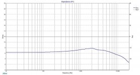
The impedance drops below 2 ohms at 2-3Khz, it is usual to try to stay above 3-4 ohms, a decent solid state amplifier should handle this low impedance, but there is another unknown here.
What does the electrical phase angle do at that frequency. If it is getting past 45 degrees it might be sensible to rejig your values, you may have to compromise the sharpness of your reverse polarity null to get the impedance back up, or maybe shoot for another slightly different crossover frequency where the impedances behave better. Go to one of your components in the tweeter and watch the resistance change as you change the component value, bring it up slightly then swap to the woofer and change one of fits components to raise the impedance slightly. Now what does the reverse null look like. try this a few times to see what you can achieve.
If you have a valve amp with 4 or 8 ohm taps I would certainly look to get the impedance back up to 4 ohms and check the phase for benign low values.
Have fun with the simulations.
Last edited:


Hi Bcrazy,
Yes, better impedance at the crossover frequency, which has moved up to 4 KHz now and the reverse null is not so sharp. Additionally the impedance at 20Khz is getting lower.
You followed my advice and you have come up with a solution, if you have tried it how did it sound to you? If you think it is stunning and your partner or kids like it, and you can listen to it for hours without getting a headache maybe leave it just there and enjoy.
I am struggling with woodwork at the moment, otherwise I could model this myself and give you some more guidance and words of encouragement.
What is happening now is that you are effectively voicing the speaker, each change ideally needs to be listened to measured and notes taken, and then try a component change.
Looking at the new shape of the frequency response, it possibly could be a bit hot around 1-2Khz, or it may it sounds good and incredibly detailed with voices. Possibly a component change here could be to go up in inductance from the 0.68mH to 0.8 or 1 mH and listen. Changing the inductance to a higher value, should roll of the midbass a little more and flatten the area around 1-2Khz, at the same time it might give you a better reverse null to the tweeter.
Finally, maybe play around with the tweeter attenuator resistors one change on the top branch and one change in the parallel branch, to see if you can keep the tweeter frequency response shape as is but get the impedance at 20 KHz back up to 4 ohm.
With all this use of the simulation, you will start to get a feel for how the component changes interact with the drivers response.
Good luck and Merry Christmas.
It's hard to say but to me it looks definitely better with the impedance curve on your last simulated crossover point. I think one thing you need to look at is the crossover point you should have a slight dip because of front baffle diffraction. Without knowing how big your baffle is and the placement of your tweeter on the front baffle it's hard to figure out how to fine tune your crossover.I usually like to play with third order crossovers because I can fine tune the crossover with small inductors and get a very clean impedance/Phase transition. Do not underestimate the need for a small dip because your speakers will sound bright and fatiguing otherwise.
gzubeck3 spotted it.
The observation about baffle step/diffraction loss what ever people want to call it is a fundamental.
With the 0.6mH value I think you can see it at 400-800Hz, and this could sound wonderful with well projected voices and certain instruments, but where has the bass gone, and the chestiness of some male voices? The original value of 1.8mH seems to flatten the response nicely, so maybe no less than 1.3mH or 1.5mH here, with 1.8 being seen as a reference. Try the new values and play with the parallel capacitor at the same time they are all interactive, infact put a resistor in series with the capacitor in the parallel bassmid leg and see how that effects the rollof. The added resistor can be very useful in adjusting the rolloff knee and the phase which can give a good match to the tweeter.
All of this is an indication that to get a crossover to sing can take minutes on a computer but hours of related listening to verify.
I am going to try to fix my woodworking errors now so good luck to both of us !!
I will try some changes during the week.
Baffle widht is 22 cm.
What i find frustrating is that the simulation now shows a perfect null at the crossover frequency , but not so when measured.
I measure at 1 meter in tweeter height, in a "normal" basement living room.
I measured the transducers without crossover in the box, and use those frd's for simulation.
I have also measured the impedance of both instrument, with a generator and voltage meter.
I will try some changes during the week.
Baffle widht is 22 cm.
What i find frustrating is that the simulation now shows a perfect null at the crossover frequency , but not so when measured.
I measure at 1 meter in tweeter height, in a "normal" basement living room.
I measured the transducers without crossover in the box, and use those frd's for simulation.
I have also measured the impedance of both instrument, with a generator and voltage meter.
I wouldn't be to caught up on how the measured responses are but after tweaking to get close how do the speakers actually sound. The reason why I use a third order crossover is that I can fine tune the transition between the the woofer and tweeter as well as increase the roll off from 12db to 18db. I found that actually playing around with a second inductor helps with phase shifts and also improves the impedance curve which then helps with sounding smoother. I mentioned that after extensive testing by the BBC that they determined that the best sounding speaker has a slight v shape around the crossover region. This is called the BBC dip. Second order crossovers have their limitations as you only have two components to work with on the woofer and tweeter. The L-pad with the two resistors can actually help you out more but you may have to be willing to play with many combinations to tweak the tweeter side of the crossover. I would concentrate more on listening tests especially playing loud and see if your experiencing fatigue. For me the tradeoffs are better to go to a third order vs. a second order because of component limitations. The benefits out way the negatives of adding another component to the chain.
Could you attach the frd's and zma's of the units here? You should either zip or rename these as textual files.
View attachment Sammi 25 bt no filter in box 1 meterfrd.txt
View attachment H404 in box no filter 1 meterfrd.txt
View attachment SammiBT25imp.txt
View attachment seasH404imp.txt
Poor correlation of null will probably be down to acoustic phase or not accurate enough mic positioning.
When you say you did a measurement on the tweeter axis did you also measure the bassmid on the same tweeter axis? If so the phase should be sensible. Others will speak up if I am wrong here. If you measured both units on their own axis this could be the problem.
Lojzek is on the case waiting to help, maybe you could publish your files? Baffle width of 22cm helps, what is the height and basic position of drivers on baffle.
This is going to be interesting as you have lived with these speakers for some years, so even if we hit a real sweet spot in terms of a technical solution you may need some time to adjust to the new sound.
Regards,
Ray.
Can you please go over your data.
The frd's are workable but the impedance seems odd, I haven't tried in Virtuix yet or Xsim yet, consequently maybe the problem is my software. I am happy it works with Clio pocket exports as that is what I use for my own stuff.
I will see what they look like in other programmes.
The frd's are workable but the impedance seems odd, I haven't tried in Virtuix yet or Xsim yet, consequently maybe the problem is my software. I am happy it works with Clio pocket exports as that is what I use for my own stuff.
I will see what they look like in other programmes.
I did measure the woofer on tweeter axis.
Attached is the frd of woofer measured on the tweeter axis. It is pretty much the same.
View attachment H404 in box no filter 1 mter, tweeter axis.txt
Attached is the frd of woofer measured on the tweeter axis. It is pretty much the same.
View attachment H404 in box no filter 1 mter, tweeter axis.txt
I don't know if your familiar with working on frd and zma files. I found a youtube video from 123toid that explains what the frd and zma files do and where they can be found. Your impedance files are not in a format in which we can import them into a crossover simulator. I'm using winpcd for a sim.
YouTube
David Ralph's Speaker Pages - Windows Passive Crossover Designer (WinPCD)
YouTube
David Ralph's Speaker Pages - Windows Passive Crossover Designer (WinPCD)
I didn't have a problem with importing data, however your naming woofer and tweeter FRD's could be wrong but that is obvious when you load the data so no real issue.
Imp impedance just doesn't look right on the previews or once imported the bassmid has two bumps for example is the design a reflex? that wouldn't be the end of the world but something goes strange around 1K ish.
Imp impedance just doesn't look right on the previews or once imported the bassmid has two bumps for example is the design a reflex? that wouldn't be the end of the world but something goes strange around 1K ish.
None of the impedance files have phase data, and the frequency response files have all zero values for phase. These need to be computed separately in a Response Modeler, for instance. I recommend ARTA labs to easily record impedance with just a simple jig made out of a single resistor and some wires. You can see the TW impedance falling at higher frequencies which is a sign of multimeter FR decline. Below the 1,000 Hz there is no data, XSim just filled in.
Attachments
Last edited:
might be worth a look at:
http://www.humblehomemadehifi.com/download/Humble Homemade Hifi_Mezzo Proteus.pdf
http://www.humblehomemadehifi.com/download/Humble Homemade Hifi_Mezzo Proteus.pdf
- Status
- This old topic is closed. If you want to reopen this topic, contact a moderator using the "Report Post" button.
- Home
- Loudspeakers
- Multi-Way
- Seas CB17RCY (H404) and Sammi DT25B50 crossover advice