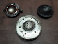
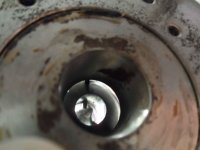
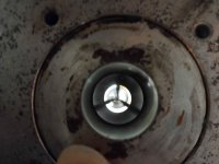
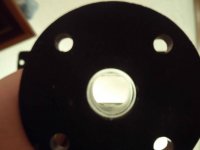
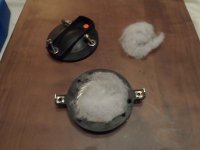
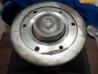
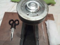
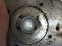
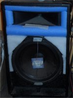
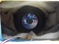
Case: both horn and compression driver are unknown model of unknown brand. These were found in 1980s Ecler TRO-120 Speakers. Re=10 ohm, 1.75" titanium diaphragm, dented suspension, axial slots and mixer, 1" exit. Oversized magnet. (fig.1, fig.2, fig.3)
(Measurement: Focusrite 2i2, Behringer ECM8000 on stand, SpecraPlus)
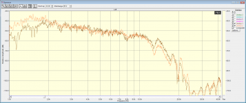
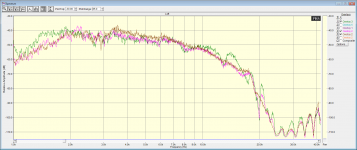
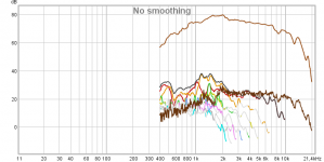
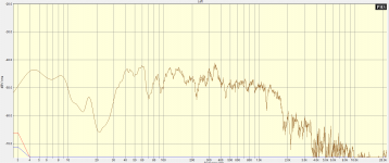
- Unmodified response: brown trace (fig.6): severe high Q dips in HF output (8Khz, 13Khz, 17Khz, 19Khz, 20Khz).
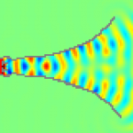
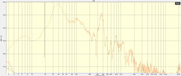
- What starts turbulent ends turbulent: Standing waves can ruin HF horn response (fig.7).
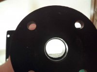
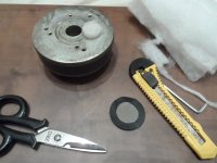
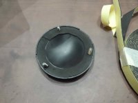
- Horn has sharp borders on cavity perimeter (fig.4). (I suppose the horn is an "eye copy" from another classic model, which includes a bullet piece. Precision in machining suggests China. In practice these borders are creating standing waves at HF.)
- Horn machined to remove borders (fig.5): orange trace (fig.6): 19Khz dip is removed, more low end output, less 14Khz peaking.
(Measurement: Focusrite 2i2, Behringer ECM8000 on stand, SpecraPlus)
- Unmodified response: brown trace (fig.6): severe high Q dips in HF output (8Khz, 13Khz, 17Khz, 19Khz, 20Khz).
- What starts turbulent ends turbulent: Standing waves can ruin HF horn response (fig.7).
- Horn has sharp borders on cavity perimeter (fig.4). (I suppose the horn is an "eye copy" from another classic model, which includes a bullet piece. Precision in machining suggests China. In practice these borders are creating standing waves at HF.)
- Horn machined to remove borders (fig.5): orange trace (fig.6): 19Khz dip is removed, more low end output, less 14Khz peaking.
Attachments
-
 metal_HF_motor_1.jpg190.9 KB · Views: 770
 -
 metal_HF_motor_2.jpg96.6 KB · Views: 766
 -
 metal_HF_motor_3.jpg108.7 KB · Views: 763
 -
 metal_HF_horn_1.jpg70.4 KB · Views: 762
 -
 metal_HF_horn_2.jpg64.1 KB · Views: 776
 -
 metal_HF_removing_motor_horn_borders_mismatch.png31.8 KB · Views: 287
 -
 what_starts_turbulent_ends_turbulent.png8.8 KB · Views: 261
Last edited:
Increasing back chamber damping with poliester fiber lining (fig.1):
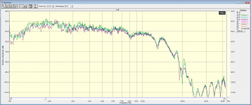
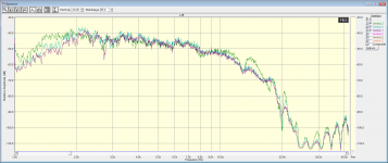
- Not lined: green trace (fig.2): Unmodified response
- Soft uniform lining: cyan trace (fig.2): reduces the 20Khz notches, but worsens the rest.
- Thick center lining: magenta trace (fig.2): splits the 20Khz notch in two.
- Not lined: green trace (fig.2): Unmodified response
- Soft uniform lining: cyan trace (fig.2): reduces the 20Khz notches, but worsens the rest.
- Thick center lining: magenta trace (fig.2): splits the 20Khz notch in two.
Attachments
Adding damping material on throat slots and mixer cavity (stranded polyester fiber made from sheet):
- Fine lining of compression chamber (no back chamber lining): no picture: loss of 3dB efficiency at all frequencies, little improvement on dips.
- Lining on throat slots (no back chamber lining, fig.1,2): cyan trace (fig.4): lots of improvement at 13Khz and 17Khz.
- Lining on throat slots. Lining in back chamber, thick at center, soft around: magenta trace (fig.4): Less 20khz dip. Slightly less low end output.
- Lining on throat slots. Soft around lining in back chamber: pink trace (fig.5): more 20Khz dip.
- Lining on throat slots. Lining in back chamber, thick at center, soft around. Lining at transition in mixer cavity (moderate density, about 1/2 wave of 20khz length, fig.3,4): brown trace (fig.5): full improvement, no sharp 20Khz dip.
There is a sudden change of expansion law at the point where both slots are mixed. It is similar to a parabolic horn in shape (very reactive acoustical impedance), 1st half expands much faster than 2nd half. This already creates standing waves (turbulent pressure waves). The mechanism is very sensitive to phase mismatch between slots due to propagation delay of the dome. The acoustical output impedance of that thing is loaded with the relatively huge mass of air inside the horn.
But there is something else, there is a bend in the path of outer slot. The edges on the bend are all subject to diffraction. Unless all parts of wave arrive in phase, some energy of the wave is radiated in all directions, including backwards, standing waves are created.
Lining: It gradually turns pressure waves, following the laws of pressure propagation, into heat waves, following the laws of heat propagation, and back. Waves propagating in many directions transition to uniform direction as they pass lining material.
Attachments
-
 metal_HF_slots_lining_1.jpg232.3 KB · Views: 289
 -
 metal_HF_slots_lining_2.jpg132.4 KB · Views: 240
 -
 metal_HF_mixer_lining_1.jpg540.1 KB · Views: 219
 -
 metal_HF_mixer_lining_2.jpg135.9 KB · Views: 216
 -
 metal_HF_slots_and_back_chamber_lining_2.png35.3 KB · Views: 229
 -
 metal_HF_slots_and_back_chamber_lining_1.png35 KB · Views: 236
Last edited:
Incidentally, I got a discouraging email from an ex-engineer of a known national pro-audio brand, which probably is the one behind the no-brand no-model compression driver.
The guy claims that no amount of fibrous material added nowhere in throat slots or compression chamber can improve sound performance.
I did further measurements and improvements to refutate that hypothesis.
A few conclussions can be derived from these measurements:
- The compression driver performs extremely good THD-wise without back chamber.
- More, overall or localized, acoustic loading is what causes more THD.
- Addition of back chamber increases lower octave THD.
- Back chamber padding with polyester fiber optimizes lower octave THD.
- The right amount of polyester fiber padding, installed just at the entry of throat slots, partially touching the dome, shifts THD lower in frequency, while correcting upper octave high-Q dips (that do not correct properly with conventional DSP, due to non "minimum-phase" nature), as already shown in previous posts.
Note: in all cases, the piece of fibrous material across the zone in slot mixer where sound waves have to bend was installed.
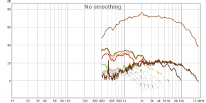
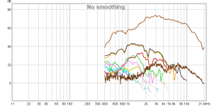
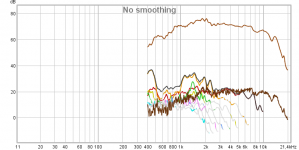
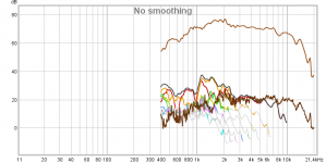
The following measurements were made all at the same microphone gain adjustment, generator set for approx. 90dB SPL, and all at same measurement distance, approx. equal to the width of the mouth of the horn, approx. 30cm.
- fig.1: No throat slot padding. No back chamber.
- fig.2: No throat slot padding. Back chamber: cover, no gasket.
- fig.3: No throat slot padding. Back chamber: cover, gasket.
- fig.4: No throat slot padding. Back chamber: cover, gasket, moderate padding.
- fig.5: Throat slot: too much padding. Bach chamber: cover, gasket, moderate padding.
- fig.6: Throat slot: slightly too much padding. Bach chamber: cover, gasket, moderate padding.
- fig.7: Throat slot: optimum padding. Bach chamber: cover, gasket, moderate padding.
- fig.8: Back chamber cover came with no gasket originally. Adhesive gasket installed.
The guy claims that no amount of fibrous material added nowhere in throat slots or compression chamber can improve sound performance.
I did further measurements and improvements to refutate that hypothesis.
A few conclussions can be derived from these measurements:
- The compression driver performs extremely good THD-wise without back chamber.
- More, overall or localized, acoustic loading is what causes more THD.
- Addition of back chamber increases lower octave THD.
- Back chamber padding with polyester fiber optimizes lower octave THD.
- The right amount of polyester fiber padding, installed just at the entry of throat slots, partially touching the dome, shifts THD lower in frequency, while correcting upper octave high-Q dips (that do not correct properly with conventional DSP, due to non "minimum-phase" nature), as already shown in previous posts.
Note: in all cases, the piece of fibrous material across the zone in slot mixer where sound waves have to bend was installed.
The following measurements were made all at the same microphone gain adjustment, generator set for approx. 90dB SPL, and all at same measurement distance, approx. equal to the width of the mouth of the horn, approx. 30cm.
- fig.1: No throat slot padding. No back chamber.
- fig.2: No throat slot padding. Back chamber: cover, no gasket.
- fig.3: No throat slot padding. Back chamber: cover, gasket.
- fig.4: No throat slot padding. Back chamber: cover, gasket, moderate padding.
- fig.5: Throat slot: too much padding. Bach chamber: cover, gasket, moderate padding.
- fig.6: Throat slot: slightly too much padding. Bach chamber: cover, gasket, moderate padding.
- fig.7: Throat slot: optimum padding. Bach chamber: cover, gasket, moderate padding.
- fig.8: Back chamber cover came with no gasket originally. Adhesive gasket installed.
Attachments
-
 metal_HF_back_chamber_gasket_1.jpg112 KB · Views: 217
 -
 metal_HF_THD_slot_optimum_padding.png37.7 KB · Views: 175
 -
 metal_HF_THD_slot_slightly_too_much_padding.png37.3 KB · Views: 132
 -
 metal_HF_THD_slot_too_much_padding.png43.2 KB · Views: 123
 -
 metal_HF_THD_no_padding_back_chamber_gasket_padding.png40.9 KB · Views: 121
 -
 metal_HF_THD_no_padding_back_chamber_gasket.png42.8 KB · Views: 130
 -
 metal_HF_THD_no_padding_back_chamber_no_gasket.png42.4 KB · Views: 189
 -
 metal_HF_THD_no_padding_no_back_chamber.png36.3 KB · Views: 212
Last edited:
The whole design is low tech hehe
But the addition of elementary fiber technology on top of elementary metal technology produces quite reasonable audio performance, as for "now and forever" good sounding low cost models.
(I did not tell which brand was, however I can give one hint, it has been the supplier of loudspeakers to Television Española for many years.)
It really doesn't matter what brand is it. If it is renowned now, it is renowned for a reason. In PRO-audio world - if quality isn't there you go down very fast.
If you have access to the 3D printer, there's whole thread here about making better phase plug that will distribute pressure more evenly.
If you have access to the 3D printer, there's whole thread here about making better phase plug that will distribute pressure more evenly.
Thanks for sharing your test. That's a lot of work to put all this together. I've done similar experiments to the Fane CD131. I actually cut a big 1.38" hole in the rear cover of the compression driver. I then stuffed insulation into the rear chamber. I noticed a significant improvement in SQ each time my modification went further. I didn't however look at the frequency response since it would tell me very little. I looked at the spectrogram images. This clearly showed reduced decay times within the first 5 milliseconds. I also looked very closely at the impedance curve using the DATS V2 tester. Cutting the big hole in the back cover reduced the FS from 1200 Hz to 900 Hz. Adding the insulation reduced the two large peaks in the impedance curve by about 50%. In the end I decided not to use this particular compression driver because it just didn't sound good enough subjectively, but it was a fun experiment.
It seems that a vented or oversized back chamber is beneficial in many cases. I know the Radian 745Neo has a small vent on the back cover. Not sure if any other modern drivers have that.
Ahh, notice the vent;

")
It seems that a vented or oversized back chamber is beneficial in many cases. I know the Radian 745Neo has a small vent on the back cover. Not sure if any other modern drivers have that.
It might be of interest that the following patent is also showing a large back chamber on a low distortion horn driver:
US4152552A - Horn speaker and method for producing low distortion sound
- Google Patents
Regards
Charles
Last edited:
Actually the more it touches the diaphragm, the worse THD becomes. Germans will never understand fluids. Fibrous material helps waves to bend.
This is so not cool.
Cheapo:
- Diffraction control for HF shortened horns.
- Horn impedance peak control for HF shortened horns.
- Phase plug for HF in big diameter cone drivers with tendency to beaming (plus cone treating with latex and back side polyester foam for damping and keeping MF/HF away from reverberating inside enclosure).
Achieved empirically with soft materials.
(Plus "tline behaving" LF resonator, finding optimum place for port entry inside enclosure.)
(Dirt & cheap because I had to move my stuff 2 times in past 6 months.)
Attachments
Slightly truncated and off-topic, but following same methodology as for HF.
- Port response measured half-way through port. No modes. Only mode is vertical enclosure resonance, well below port response. Works 300Hz downwards.
- In-room response measured in front of speaker, with LF boost to level "extended-bass-shelf" down to 30Hz. Wooden floor and furniture nearby.
- Port response measured half-way through port. No modes. Only mode is vertical enclosure resonance, well below port response. Works 300Hz downwards.
- In-room response measured in front of speaker, with LF boost to level "extended-bass-shelf" down to 30Hz. Wooden floor and furniture nearby.
Attachments
Last edited:
- Status
- This old topic is closed. If you want to reopen this topic, contact a moderator using the "Report Post" button.
- Home
- Loudspeakers
- Multi-Way
- Tweaking metal dome compression drivers and HF horns for hi-fi response. Case study.