Midwoofer in open-baffle or cardiod will match the directivity lower – at 700 or 800Hz.You can't really, that's why I use the 15". The 8" will always be wider than the waveguide unless you cross very high up, which is not ideal as the polar errors grow as the frequency goes up. Sorry, but 15" really is the better choice - lower crossover, less lobing, better match.
Jacek,
Is your 3D printer churning away on Marcel's latest WG as we speak...?
It's too small (Zortrax M200)
I've sent to test print on professional printer.But I printed 12" wg for AMT with back chamber based on Marcel's work. Will be tested by friend with custom Beyma 12".
Midwoofer in open-baffle or cardiod will match the directivity lower – at 700 or 800Hz.
I was always interested to try baffle 0,6m wide 1 meter tall with waveguide that has comp driver with open back to another waveguide and rest also dipole.
Anyone?
I was always interested to try baffle 0,6m wide 1 meter tall with waveguide that has comp driver with open back to another waveguide and rest also dipole.
Anyone?
The asymmetry of a compression driver would mean you need to have a very different rear-facing design, and the design and assembly complexity would be astronomical. Better to just use a second driver/waveguide combo in my opinion.
Midwoofer in open-baffle or cardiod will match the directivity lower – at 700 or 800Hz.
I think that people over estimate the effect of an open baffle on a drivers directivity. Once the driver begins to narrow its coverage, the baffle no longer has a significant effect. This means that the driver has the same beam-width at crossover whether its open baffle or not (unless the driver is very small, in which case it won't work very well open baffle.)
I thought about lowering the crossover point. You said it's better to cross at 1000-1100 region to better match directivity. My idea was the OB will maintain narrow directivity down to lowest frequencies and thus will make 700Hz crossover possible.I think that people over estimate the effect of an open baffle on a drivers directivity. Once the driver begins to narrow its coverage, the baffle no longer has a significant effect. This means that the driver has the same beam-width at crossover whether its open baffle or not (unless the driver is very small, in which case it won't work very well open baffle.)
I thought about lowering the crossover point. You said it's better to cross at 1000-1100 region to better match directivity. My idea was the OB will maintain narrow directivity down to lowest frequencies and thus will make 700Hz crossover possible.
I think where it can get more challenging is that the driver directivity from dipole/cardioid is effective where the driver's operating in more of an omnidirectional mode. As the driver naturally starts tapering in directivity, it no longer cancels to the sides, and depending upon the details, you may get a dispersion flare from where the cancellation is taking place, to where the driver's natural directivity keeps it narrow.
I think it's doable just with lots of effort and impractical for most systems. Even though Geddes style solutions are a little more complex than plug 'n play, adding dipole EQ and all the extra stuff that goes along with a dipole/cardioid solution adds a lot more complexity and equipment.
Almost anything is possible with enough effort, a big enough room, and a big enough budget, but there's always an economic decision to be made about whether all that adds something meaningful enough to pursue.
I think it's doable just with lots of effort and impractical for most systems. Even though Geddes style solutions are a little more complex than plug 'n play, adding dipole EQ and all the extra stuff that goes along with a dipole/cardioid solution adds a lot more complexity and equipment.
Having been down this road with paper studies I can tell you that the complexity gets to the point of impractical.
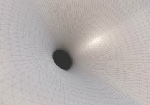
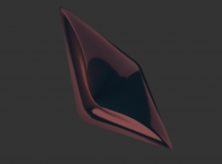
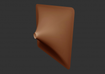
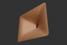
I found some more pictures of the "rectangular" profile including cuts around the circumference. I'm willing to release the tool if anyone is interested. I could incorporate a functionality of generating of complete ABEC project with a mesh file so everyone could easily "design and try" their own. Any interest?
Attachments
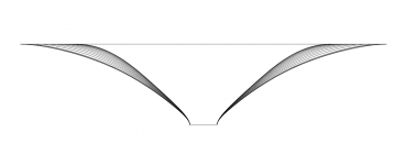
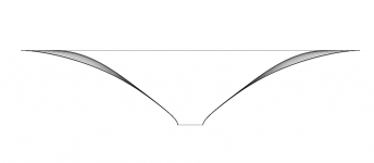
That is something still to be figured out and which I hope someone will show later on. I don't work with any 3D CAD myself and I have no clue what the possibilities are, I only know it can be done. All I'm able to do is to export coordinates of the points in some form. These can be imported to CAD and then splines, surfaces and volumes created. We already tried this with jzagaja and it worked with satisfactory results. I can create directly only triangular meshes and STLs...
Hold on, I'm finishing the tool to be released. I began to use Gmsh API internally so it's really easy to add any mesh for ABEC, including a (rounded) box for the waveguide, etc.
Hold on, I'm finishing the tool to be released. I began to use Gmsh API internally so it's really easy to add any mesh for ABEC, including a (rounded) box for the waveguide, etc.
Last edited:
Well done mabat! I would really apreciate if you choose to share the ABEC project as I am learning the software myself.
Importing points into CAD and creating a solid model for CNC or 3D printing will not be very difficult.
I have been working with waveguides about 10" in size in ABEC and had to move away from OS to obtain nice polars. Interesting to see your results in this regard.
Importing points into CAD and creating a solid model for CNC or 3D printing will not be very difficult.
I have been working with waveguides about 10" in size in ABEC and had to move away from OS to obtain nice polars. Interesting to see your results in this regard.
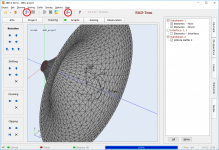
I just need to write some short user guide. In the meantime you can try these two sample projects. All you have to do (provided you already have VACS and ABEC3 on your computer) is to load the project file to ABEC and push the two buttons in the toolbar (left first) to see how good it can get.
These are some quick ABEC projects just created by the tool. One OSWG and a rectangular-morphed horn. Calculated are horizontal, vertical and diagonal polars and a radiation impedance, for the start. You can inspect the *.msh files with Gmsh (Gmsh: a three-dimensional finite element mesh generator with
built-in pre- and post-processing facilities)
Once I have it ready I will start a new thread.
Attachments
- Home
- Loudspeakers
- Multi-Way
- 1.4" or 2" throat large constant directivity horns you can actually buy!