np, that's the one I am using too (in post #120).
You see in the jbl plots of 6212 and 4212/00 that it is a little less wide dispersion horizontally (the bubble in the throat).
Think I stole dualtriode's pic.
I am not unhappy with what I have, just curious about the newer one.
You see in the jbl plots of 6212 and 4212/00 that it is a little less wide dispersion horizontally (the bubble in the throat).
Think I stole dualtriode's pic.
I am not unhappy with what I have, just curious about the newer one.
100 x100
RobH:
I'm hoping to do this passive, but want to get something worked out that sounds good using as much of my stuff on hand as possible. I know next to nothing about crossovers, so it really limits what I can accomplish.
In my previous post, I had a typo...my crossover is a TDM model 24-CX-4. All balanced. I have a 7 channel JBL Synthesis amp sitting here unused at the moment. To restate my objective, I have these vintage EV speakers with really nice mahogany cabinets, 3.14 cubic feet internal volume. Alnico magnet woofer. Have the 2344a and 2404H on hand.
If it was easier to implement, I'd be be glad to purchase a different waveguide, such as the ones you and Norman Bates are discussing. My cabinetmaker was here yesterday on a different project, and we discussed making some stands to get the speakers up off the floor a couple inches, and to add a framework to support the 2344a and the 2404h. To experiment., I'll just cut up a piece of scrap wood though. If they sound good, I'll take the next steps, and get help with a proper passive crossover.
Rolloff of 2344a
RobH:
I need to understand this in a slightly different light; if you run the 2344a full range without any type of compensation, and just let it roll off, would a simple high pass protect the 2404H from damage? High passed at a higher level, as many suggest on the Lansing forum...say 7-8khz?
Thanks!
Hello All,
Some may be wondering about matching the crossover frequency of your woofer or midrange cone driver to match the nominal 100 X 100 coverage pattern of your waveguide The old 1010 is a little wider than 100 degrees. The new 1010 is pretty much square at 100 X 100 degrees. The M2 waveguide is a bit wider at near 120 degrees.
Not to get into the weed I will speak to a nominal 100 X 100 degrees. Take a look at Figure 3 in the linked Altec Lansing Tech Letter Number 237. This graphic shows the degree of coverage for a piston (cone) driver; size vs frequency. Measure your driver diameter center of surround to center of surround. This measurement is smaller than the outside diameter of the driver. My 8 inch JBL 2119H is 6-17/32 inches, the diameter of the piston, not the nominal 8 inch OD. On Figure 3 draw a line at 6-17/32 inches between the 8 inch line and 6 inch line. This new line for the 8in Mid crosses the 100 degree line at ~ 2.2KHz. Do the same line drawing for a 15in driver, a 12in driver and a 10in driver.
-6dB crossover frequencies for cone drivers to match the -6dB format of the 100 X 100 waveguides.
8in ~ 2.2KHz
10in ~ 1.6KHz
12in ~ 1.4KHz
15in ~ 1.2KHz
Remember that if your waveguide is a little wider than 100 degrees then you may want to crossover a tad bit lower.
Thanks DT
http://alteclansingunofficial.nlenet.net/publications/techletters/TL_237.pdf
I wrote some MATLAB/OCTAVE to solve this directivity matching problem:
I can't remember exactly what I was up to but it gives you at least polar maps")
***edit seems to be some kind of error in the code as the results don't seem right, will have a look later
I can't remember exactly what I was up to but it gives you at least polar maps
***edit seems to be some kind of error in the code as the results don't seem right, will have a look later
Code:
%Assumes flat piston on infinite baffle

f = [20:10:1250]; %Frequencies of interest [Hz]
theta = [0:1:359]; %Angles of intrest
dia = 0.381; %Piston diameter [m]
v = 344; %Speed of sound [m/s]
k = f.*2.*pi./v; %wavenumber (2pi/lambda)
ka = dia/2*k; %radius * wavenumber
angle_match = 90; %directivity angle we are trying to match to

%Plot ka
figure(1)
plot(f,ka);
xlabel('Frequency [Hz]');
ylabel('ka');

%Generate polar maps for the piston
p_test = zeros(length(ka), length(theta));
for loop=1:length(ka)
  p_test(loop,:) = real(2*besselj(1,ka(loop).*sin(pi*theta/180))./(ka(loop).*sin(pi*theta/180)));
end;

%Find frequency where amplitude is -6dB at desired angle to match horn
%do this by incrementing the angle match until we are -6dB
f_match = 0;
for loop=1:length(f)
  p_angle_match(loop) = real(2*besselj(1,ka(loop).*sin(pi*angle_match/180))./(ka(loop).*sin(pi*angle_match/180)));
  if ((p_angle_match(loop) <= 0.25) && (f_match == 0)) %-6dB
    f_match = f(loop);
  end;
end;


figure(2)
polar(theta*pi/180,p_test(100,:));

figure(3)
plot(f,p_angle_match);
Last edited:
Hello,
All that math and programing is baked into the cake and included in Figure 3 in the linked Lansing Tech Note. The goal was to keep it simple.
While you are sorting the MATLAB script.
Before I get lost in the details of converting radian to degrees I like to run a couple of sample calculations on the whiteboard. Just to remind myself of things like the angle of coverage, 100 X 100, is plus and minus theta. Theta is 50 degrees.
k a sin (theta) = 2.2 for -6dB
Thanks DT
Yea, rule of thumb.
8" @ 2khz
12" @1.2khz
15" @ 800hz
Even then, it is nice to have even better dispersion.
My solstice crosses a dome to a 6" @ 1.75khz.
Sounds great almost 90 degress off axis !!!!!!!
Better dispersion, what is that?
I thought the goal is to cross over at the frequency where the waveguide and cone driver have as close as possible to equal matching directivity.
Your rule of thumb values are more closely matched to 120 degrees than 100 degrees. More like the M2 or old 1010 waveguides than the new 1010.
Very much like I said a couple of posts ago.
If you like you can do the calculations.
Thanks DT
Added thought: Some woofers / cone drivers may not make it to 100 degrees dispersion before they begin to break-up and and have resonance peaks. Example: Peerless SLS 830669 - 12" Woofer - Coated Paper Cone
Last edited:
True.
The am5212/7212/00 cross at 1.6khz and 1.5khz, to a 12".
Semi same dispersion is good.
I'm a bit more focused on a "clean" horn.
Hello,
I agree there are other considerations in addition to a smooth directivity curve and power curve.
The drivers need to behave well above and below the crossover frequency for an octave or so depending on filter slopes. For passive filter slopes you are likely at 12dB slopes. I am using a LR active 24dB active crossover.
This coming up week I am going to get some more bench time to test a couple of Compression Driver and Waveguide combinations for impedance and frequency response.
How does 500Hz to 22KHz sound?
Thanks DT
RobH:
I need to understand this in a slightly different light; if you run the 2344a full range without any type of compensation, and just let it roll off, would a simple high pass protect the 2404H from damage? High passed at a higher level, as many suggest on the Lansing forum...say 7-8khz?
Thanks!
It might work but you really need to either sym it or try with DSP or an active set up. Passive is hit or miss and without measurements and a good crossover sym program it may be doable but it's going to end up being trial and error to get there. No matter what, you need to work out the attenuation for both the 2344 and the 2404 or you won't be able to get them to sum properly
Rob
Last edited:
500hz ?
For the pt ?
I think they only "load" to 1200-1500.
The newer pt is 3" deep.
Eek, i wouldn't cross my 2384 (way bigger horn) with 2435hpl below 750hz.
Your 4" diaphragm may get there, idk.
Thanks for all your work.
It takes a bit.
And graphs with the same compression different horns show much.
For the pt ?
I think they only "load" to 1200-1500.
The newer pt is 3" deep.
Eek, i wouldn't cross my 2384 (way bigger horn) with 2435hpl below 750hz.
Your 4" diaphragm may get there, idk.
Thanks for all your work.
It takes a bit.
And graphs with the same compression different horns show much.
Last edited:
Ahhhhhhhh, ok.
I think rob got his older pt horn plus 2435hpl (3" diaphram) down to 1khz with no eq boost, just hf boost for it.
Too bad the older pt is $150 while the newer is $75 (basically after shipping).
Foam around the older pt horn sounds really good to my ears.
It doesn't do much wrong at all.
Norman
I think rob got his older pt horn plus 2435hpl (3" diaphram) down to 1khz with no eq boost, just hf boost for it.
Too bad the older pt is $150 while the newer is $75 (basically after shipping).
Foam around the older pt horn sounds really good to my ears.
It doesn't do much wrong at all.
Norman
Hello All,
Had a good couple of days testing things, would have tested more but went to the beach instead.
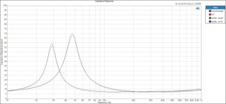
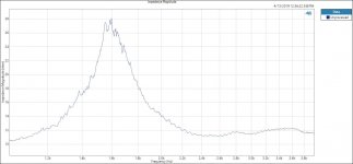
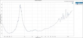
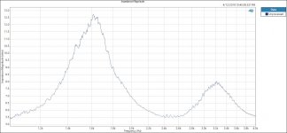
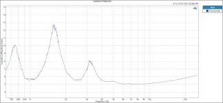
Tested TS / P for several woofers trying out for the woofer job in my new mains project, results are saved on a thumb drive. See the sample curves and TS /P for the 2204H.
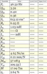
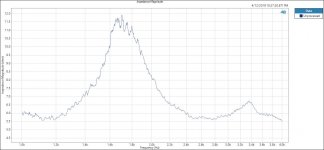
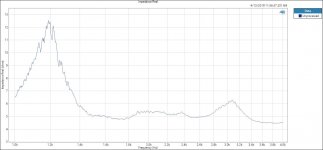
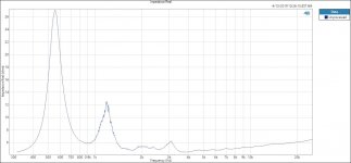
Tested impedance with the PT H1010HF-1 waveguide (the new one) with several drivers; 2432, 2451J and D2. I will post these in this thread.
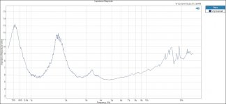
Also tested the smaller version of the JBL Butt Cheeks the 2342 with a 2425HS driver. I will also post this one.
One thing worth noting is that the impedance plots for the cone drivers and CD / waveguide look completely different. In my head this helps explain the reason that cones and horns sound different.
Similar to the cones all of the CD / Waveguides have what I call a voice coil impedance / resonance peak. The CD / Waveguides also have what Rob calls a Throat Mouth impedance / resonance peak.
Another thing in the CD / Waveguides curves absent in the cone curves is what I call Micro Resonances. At first glance they look like sort of random saw teeth. I plotted and replotted the CD / Waveguides curves many times on the same graph. Each plot fell exactly on top of the previous plots with each MR exactly matching the previous plots. These MR’s are not random noise or artifact.
Attachments are:
JBL 2204 H impedance curves; in air and with added 93.5 gram weight and TS / P table.
JBL PT H1010HF-1 with JBL 2432H driver; Full band width and zoomed in 1K to 4KHz.
Thanks DT
Had a good couple of days testing things, would have tested more but went to the beach instead.
Tested TS / P for several woofers trying out for the woofer job in my new mains project, results are saved on a thumb drive. See the sample curves and TS /P for the 2204H.
Tested impedance with the PT H1010HF-1 waveguide (the new one) with several drivers; 2432, 2451J and D2. I will post these in this thread.
Also tested the smaller version of the JBL Butt Cheeks the 2342 with a 2425HS driver. I will also post this one.
One thing worth noting is that the impedance plots for the cone drivers and CD / waveguide look completely different. In my head this helps explain the reason that cones and horns sound different.
Similar to the cones all of the CD / Waveguides have what I call a voice coil impedance / resonance peak. The CD / Waveguides also have what Rob calls a Throat Mouth impedance / resonance peak.
Another thing in the CD / Waveguides curves absent in the cone curves is what I call Micro Resonances. At first glance they look like sort of random saw teeth. I plotted and replotted the CD / Waveguides curves many times on the same graph. Each plot fell exactly on top of the previous plots with each MR exactly matching the previous plots. These MR’s are not random noise or artifact.
Attachments are:
JBL 2204 H impedance curves; in air and with added 93.5 gram weight and TS / P table.
JBL PT H1010HF-1 with JBL 2432H driver; Full band width and zoomed in 1K to 4KHz.
Thanks DT
Attachments
I think rob got his older pt horn plus 2435hpl (3" diaphram) down to 1khz with no eq boost, just hf boost for it.
Hello Norman
I don't use "hf boost" like you would use in a Pro S/R set-up. There is no reason to in a home application as it really is a worst case scenario for a compression driver. Even my bi-amp setups use a passive compensation network.
When you use an active set-up with a CD compensation curve you can end up with 10db or more of boost up there to compensate for the mass break point roll off of the driver. It's no wonder some active set-up's really get harsh or glaring as the volume goes up.
The better way is to loose efficiency midband and use a passive network to reduce the lower end of the drivers response to match the woofer and get a "flat response" that way. You end up driving much less power into the compression drivers upper octaves, a couple of watts vs 10X as much if you go active boost.
Rob
Last edited:
- Home
- Loudspeakers
- Multi-Way
- JBL PT 100x100 waveguides, any experience? MPro?