I think this will answer both your questions Phase, Time and Distortion in Loudspeakers
When looking for an easy explanation, I refer to 'Loudspeakers' by Gilbert Briggs.
"Some listeners notice a 'feathery' effect when the speakers are out of phase. As the frequency rises, the importance of phasing gradually recedes due to the shorter wavelength. With a crossover at 4,000Hz, where the wavelength is only 3", the question can be ignored."
If you are interested in the phase shifts introduced by different orders of crossover network, and solutions such as reversing the leads to the tweeter or setting it back the required fraction of a wavelength in the baffle, then more reading is required!
Passive crossover network explanation | Audio Judgement
Your primary concern is being aware of it, so that you can bring two bands together as intended and combine their response in a controlled way.is it something I can clearly hear, what do I look out for?
Indeed, a seamless splice of output from the two drivers is the goal.
The theory is that our test functions of sine waves change phase along with acoustic amplitude according to some very ancient algebra of complex numbers. It's called Fourier Transform.
One popular solution is the 4th order LR4 function.
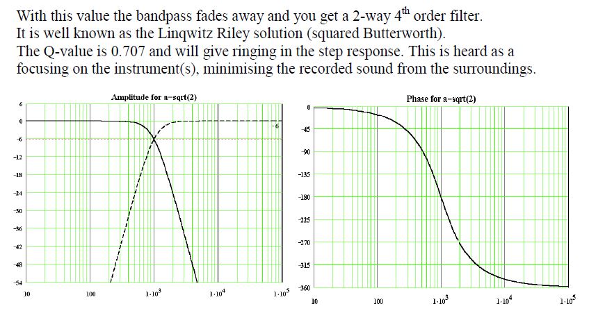
It's actually assuming time alignment between the bass and tweeter, which doesn't always happen in the real world. I mentioned a simulator in another of your threads. They are useful.
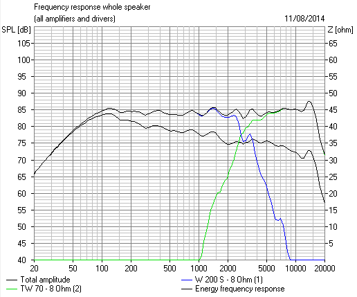
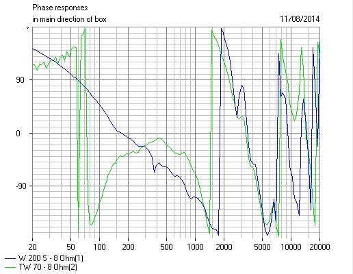
That is very good phase alignment, though I say so myself. Should integrate well on axis.
The theory is that our test functions of sine waves change phase along with acoustic amplitude according to some very ancient algebra of complex numbers. It's called Fourier Transform.
One popular solution is the 4th order LR4 function.
It's actually assuming time alignment between the bass and tweeter, which doesn't always happen in the real world. I mentioned a simulator in another of your threads. They are useful.
That is very good phase alignment, though I say so myself. Should integrate well on axis.
I don't know your level of physics knowledge, but here is a starting point for further research.As someone who is new to this, is there an easy explanation of how a crossover can alter the speaker phase?
When an alternating current flows in a resistor, the voltage across the resistor peaks at the same time as the current. The voltage and current waveforms are said to be 'in phase'.
The alternating voltage across a capacitor doesn't peak until the current is zero, so the voltage waveform is 'out of phase' with the current waveform.
The voltage waveform across an inductor is also 'out of phase' with the current waveform, but not in the same direction as a capacitor.
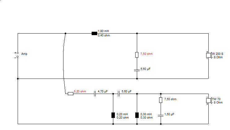
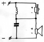
In the 1st order series crossover shown, the alternating voltages across the inductor and the capacitor will therefore not be in phase with each other. This means that the outputs from the tweeter and the woofer will not sum together as expected at the crossover frequency.
Different orders of crossovers give different degrees of phase shift and good crossover design attempts to minimise their effect.
Attachments
- Status
- This old topic is closed. If you want to reopen this topic, contact a moderator using the "Report Post" button.
- Home
- Loudspeakers
- Multi-Way
- How does a crossover alter speaker phase?