I have done some further modification options of the profile following the underlying concept.
Usually, such horns have the property that for the expanding profile all points along the horn axis of the outer shell are oriented in the same plane where at the mouth the horn is flat/flush to the speaker front/plane. I thought some time about this and found several options how the profile can be bended using the original Klangfilm construction vector r0.
The following three variants use different assumptions:
1. For every elliptical plane along the horn axis the origin of the construction vector is calculated. Then for every point of the ellipse the vector from this origin to this point is used, it's length is calculated and then normalized to r0. Then the ellipse point is slided alog this vector until the new vector has the normalized r0 length. So, the points near the major semi axis are shifted against the throat and points near the minor semi axis will be shifted in the opposite direction.

2. The same construction vector is used but only the z-component is used to shift the points.

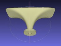
3. The angle of the construction vector is changed while leaving it's length at r0 so that it ends at the elliptical cylinder. This only changes the z-component which is the horn axis. This option leeds to some dramatic looking profiles.

Usually, such horns have the property that for the expanding profile all points along the horn axis of the outer shell are oriented in the same plane where at the mouth the horn is flat/flush to the speaker front/plane. I thought some time about this and found several options how the profile can be bended using the original Klangfilm construction vector r0.
The following three variants use different assumptions:
1. For every elliptical plane along the horn axis the origin of the construction vector is calculated. Then for every point of the ellipse the vector from this origin to this point is used, it's length is calculated and then normalized to r0. Then the ellipse point is slided alog this vector until the new vector has the normalized r0 length. So, the points near the major semi axis are shifted against the throat and points near the minor semi axis will be shifted in the opposite direction.
2. The same construction vector is used but only the z-component is used to shift the points.
3. The angle of the construction vector is changed while leaving it's length at r0 so that it ends at the elliptical cylinder. This only changes the z-component which is the horn axis. This option leeds to some dramatic looking profiles.
Finally, I have applied a stereographic projection to the profile using the construction vector r0. Like the world map is projected from the earth sphere to a plane this projection does the oppsosite.
I am quite happy with the results. Have used MeshLab to draw the surface area.


I am quite happy with the results. Have used MeshLab to draw the surface area.
Hi!
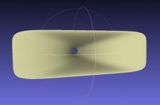
only a small teaser what will be possible with the forthcoming version of my calculator. From round to elliptical, from round to squared or rectangled, projected or not projected, nearly everything is possible...
3D printing of the first horn is in the preparation phase.
only a small teaser what will be possible with the forthcoming version of my calculator. From round to elliptical, from round to squared or rectangled, projected or not projected, nearly everything is possible...
3D printing of the first horn is in the preparation phase.
Attachments


I've seen the dip peak in symetrical horn, like the jbl sp212a, oasr horn but ripples in jbl's pdf.
Post 55
Flattest response between 2000hz - 20 000hz - Page 4
jbl sp212a - Google Search
I've been looking at the pt h1010hf waveguide that some like, there is even a newer one in plastic for under $70 (1.5" jbl). I notice jbl uses a 3khz notch with it. It is square 100 x 100 but looks fairly smooth walled for not being round.
JBL 442730-001 PTH1010HF-1 Waveguide - Speaker Exchange
Older pt 100x100
Something Old with Something New
Strangely enough, the round QSC waveguides are symmetrical but do not have that dip. I don't know how they did that:
Great Waveguide List
Hi docali,
very interesting work!
When will you show your new calculator....")
very interesting work!
only a small teaser what will be possible with the forthcoming version of my calculator. From round to elliptical, from round to squared or rectangled, projected or not projected, nearly everything is possible...
When will you show your new calculator....
I could not find that out so far although I have searched for it as well. But interestingly all published FR measurements of Faital 1.4" drivers are performed on that horn. Although not all 1.4" Faital Drivers have the same exit angle.
The Faital horn looks a little prettier than the XT1464 but I guess it will not load as low as the XT1464. That - and someone from this forum (was it AllenB ?) who also had good experiences - made me go with the XT1464 for my Faital HF146 drivers for my "kitchen loudspeakers".
Regards
Charles
It's kind of funny, the way we are concerned with driver exit and (horn) entrance angles.
Faital Pro uses the same horn (LTH-142), for the measurements of all their 1.4" drivers.
The exit angles of the conical adaption horns range from 6° (HF141 & 143), 7° (HF140), 12° (HF148 & 1400) to 29° (HF142, 144, 146).
Try to look for clues, it's mesmerizing.
For horns with a relatively low flare rate - like the LTH-142, I don't think the exit angle matters all that much. The phase plug design however, does.
I owned and sold Monacor branded samples of the LTH-142. It's a nice horn, but undersized (like most PA-horns). Compared to the XT-1464, the LTH-142 is subjectively more prone to beaming, even though the graphs may suggest otherwise. This is inherent to the Tractrix horn contour.
It's good to see docali working out somewhat bigger horns > 50cm mouth width. This appears to be a critical size, once you go beyond 50cm nearly all types of horns/waveguides really start to show their merits.
Last edited:
Now, with a small Lamé exponent: View attachment 741444
It is fascinating (to me) to modelize such complex forms, a calculator should be great.
MeshLab is fun.

Currently, I need first to verify my concept by print out such an horn and do some measurements before I will make available my calculator. Additionally, I need to protect my work in some way but not with a business scope in mind. And I want to keep some basic control. As i have done it in Excel there is no way to protect the code.
The math behind some steps is very complex like the numerical integration of the tri-axial ellipsoid surface cap. And it took a long time to make/normalize the stereographic projection work properly.
Furthermore, very much effort went into the creation of the point cloud which can be extracted automatically for Meshlab. For this the arc length of yh need to be numerically integrated and several other function for surface areas and arc lengths. The horns shown at last here were created only by changing 2 or 3 parameters in the Excel and only about 5-10 minutes in Meshlab to create the STL files. Also a material thickness could be incorporated for the use with Blenders Solidify algorithm.
I have some limited feedback from some people and this could open a complete new class of horns if the concept works.
My skills about 3D printing are still very limited. But an error free STL file should be a good start. Also the material used will be very important. But we this new industrial revelution of 3D printing and everything here is developing fast. So, maybe in a very short time we will be able ti print something that feels like wood and behaves quite similar.
numerical integration of the tri-axial ellipsoid surface cap. And it took a long time to make/normalize the stereographic projection work properly.
It looks as a huge intellectual effort, i've tried to do this with my limited (mathematical) abilities and my STL files were not really usable because of the use of recurring calculations generated by excel sheets

It could be fantastic to make some new gen coaxial transducers with an ellipsoidal motor transducer around the horn (or WG).
Here is an exemple of a round tractrix arrangement, it is a 320 Hz horn in a Ø480mm cone.


Currently, I need first to verify my concept by print out such an horn and do some measurements before I will make available my calculator. Additionally, I need to protect my work in some way but not with a business scope in mind. And I want to keep some basic control. As i have done it in Excel there is no way to protect the code.
I can understand and accept this. Seems I have to set up a respective calculation sheet by myself...
Please go on with your thread anyway.
My skills about 3D printing are still very limited. But an error free STL file should be a good start. Also the material used will be very important. But we this new industrial revelution of 3D printing and everything here is developing fast. So, maybe in a very short time we will be able ti print something that feels like wood and behaves quite similar.
3D printing quality has much improved, but you need a industrial grade printer for larger objects.

3D printing quality has much improved, but you need a industrial grade printer for larger objects.
Or you can use a cheap 3D printer and make a positive mold, then glue some fibers on it.
Diagonal, radial, diagonal, radial, diagonal, radial....

https://nsa40.casimages.com/img/2019/03/09/1903090409381253.jpg

Last edited:
@Gaga
If you tell me what horn you are searching for (cut-off, which kind of horn, etc.) then I could try to do a special calculation or point cloud.
But if you want better prepare your own calculation sheet this is highly welcome. What I have learned is that at first you need a good idea what to do and then how to do and then how to verify. You may need some advanced mathematical skill also. If you have all of this then you also need programming skill. My code has currently about 2000 lines only for this limited scope. So, it is not really an Excel sheet that does the caclulation. Excel is only used to store data and to visualize.
My experience with STL files is that you need quite evenly spaced points. This is a real challenge with some complicated functions and this fine tuning took more time than the horn profiles itself. You have to do a lot of transformations between cartesian and polar coordinates to be flexible. Integrations are often better done with polar coordinates.
Only to give you an impression look here:
https://keisan.casio.com/keisan/image/surface%20area%20of%20an%20ellipsoidal%20cap.pdf

If you understand such math then you are encouraged to proceed.
If you tell me what horn you are searching for (cut-off, which kind of horn, etc.) then I could try to do a special calculation or point cloud.
But if you want better prepare your own calculation sheet this is highly welcome. What I have learned is that at first you need a good idea what to do and then how to do and then how to verify. You may need some advanced mathematical skill also. If you have all of this then you also need programming skill. My code has currently about 2000 lines only for this limited scope. So, it is not really an Excel sheet that does the caclulation. Excel is only used to store data and to visualize.
My experience with STL files is that you need quite evenly spaced points. This is a real challenge with some complicated functions and this fine tuning took more time than the horn profiles itself. You have to do a lot of transformations between cartesian and polar coordinates to be flexible. Integrations are often better done with polar coordinates.
Only to give you an impression look here:
https://keisan.casio.com/keisan/image/surface%20area%20of%20an%20ellipsoidal%20cap.pdf
If you understand such math then you are encouraged to proceed.
3D printing quality has much improved, but you need a industrial grade printer for larger objects.
Do you know what material was used here?
- Home
- Loudspeakers
- Multi-Way
- Klangfilm spherical wave horn calculator - from round to elliptical