It looks as a huge intellectual effort, i've tried to do this with my limited (mathematical) abilities and my STL files were not really usable because of the use of recurring calculations generated by excel sheets

Was this done from JMLCs worksheet? Looks like the E-JMLC.
Was this done from JMLCs worksheet? Looks like the E-JMLC.

Yes it is, and an error in the worksheet has given me headache as you can see, please don't forget to debug... it overheat the little technicians brains.

PS : You should avoid PLA, it sucks for the planet and the parts made with it are porous junk things. If you want to have a solid concrete looking finish, here is the Strathmore drawing toned gray.
Amazon.com: Strathmore Drawing 400 Series Toned Gray Sketch Pad 5.5"x8.5" 50 Sheets: Office Products (it gives the audiophool psycological satisfation)

Last edited:
Hey, the grey looks good! Do you make it per hand or with a 3D printer?
Unfortunately, spice-time-continuum does not give me the chance to discuss my horn profiles with JMLC. I am sure we would have some great discussions. His horns were a break through for the community.
And you encountered a classical copy and paste error. My sheet works differently. The VBA code fills the cells and cleans them. So, if the code works this kind of erros cannot occur anymore. During my phd I programmed more than 100.000 lines of FORTRAN code and if you do quantum chemistry calculations then debugging is always part of the work. And believe me that a two center Slater type overlap integral is also a quite complicated thing to program
I always tested my numerical integrations with well know special cases like the ideal surface of a sphere.
Sometimes i dream about the abilty to do what you can do with my brain... and realize that i can't imagine what level of mathematical culture it requires.Hey, the grey looks good! Do you make it per hand or with a 3D printer?
Unfortunately, spice-time-continuum does not give me the chance to discuss my horn profiles with JMLC. I am sure we would have some great discussions. His horns were a break through for the community.
And you encountered a classical copy and paste error. My sheet works differently. The VBA code fills the cells and cleans them. So, if the code works this kind of erros cannot occur anymore. During my phd I programmed more than 100.000 lines of FORTRAN code and if you do quantum chemistry calculations then debugging is always part of the work. And believe me that a two center Slater type overlap integral is also a quite complicated thing to program
I always tested my numerical integrations with well know special cases like the ideal surface of a sphere.
See the world with your logical possibilities is impossible for me, please be patient

The positive mold is a plaster turned with laser cutted templates, i must be very very precise, since the horn is aligned into another transducer and the alignment error margin is under 0,2 mm.
The cellulose fibers deposit takes around 2 hours for a complete horn. There is one asymetrical antimode diagonal layer and two radial layers, the walls tickness is irregular, progessive and 1.8mm of thickness at the horn entry.
Here you can see a part of the "secret"
layers arrangement, made by two human hands in a very rigourous procedural process where everything is quantified (i always work with the eyes pointed on a detailled procedural handbook)

PS : There is no limitations for the horn shape with this process.
Last edited:
I use 2D and 3D dxf files for outsourced parts productions and OBJ and STL files for 3D printing.A very impressive procedure to make the horns! But would you please explain what cutted templates are? This is nothing a "normal" human being can use?
What do you need to make the positive mold - an STL or something similar?
It is a specific DIY lathe that permit 3 axis of adjustements, but it was a prototype designed for a specific coaxiality constraint, it is possible to make a simple positive mold with a 3D printer and a STL file or a bottle of Champagne.

And then you can reuse your mold lifelong... please take a look at the purple curve.

It's kind of funny, the way we are concerned with driver exit and (horn) entrance angles.
Faital Pro uses the same horn (LTH-142), for the measurements of all their 1.4" drivers.
The exit angles of the conical adaption horns range from 6° (HF141 & 143), 7° (HF140), 12° (HF148 & 1400) to 29° (HF142, 144, 146).
Try to look for clues, it's mesmerizing.
For horns with a relatively low flare rate - like the LTH-142, I don't think the exit angle matters all that much. The phase plug design however, does.
I owned and sold Monacor branded samples of the LTH-142. It's a nice horn, but undersized (like most PA-horns). Compared to the XT-1464, the LTH-142 is subjectively more prone to beaming, even though the graphs may suggest otherwise. This is inherent to the Tractrix horn contour.
It's good to see docali working out somewhat bigger horns > 50cm mouth width. This appears to be a critical size, once you go beyond 50cm nearly all types of horns/waveguides really start to show their merits.
I think too that the exit angle does not play that important role. But maybe it is not a so wise decision to use the mentioned 29° exit angle with a long horn. I would assume that such drivers work better with short horns or a waveguide.
I compared the LTH-142 and XT1464 with my large format 18s driver and found that the LTH142 looks more smooth but the XT1464 can go lower and loads the driver better. But both are terrible plactic bombs. I have already seen a 3D printed WE clone in Munich high end show done by Azzolina. These horns felt similar to wood and looked awesome. But is would be quite expensive to make a larger horn.
Size in no limit for calculations but you need a good printer that could print such a large thing. For my 18s driver my target cut-off is 350 Hz.
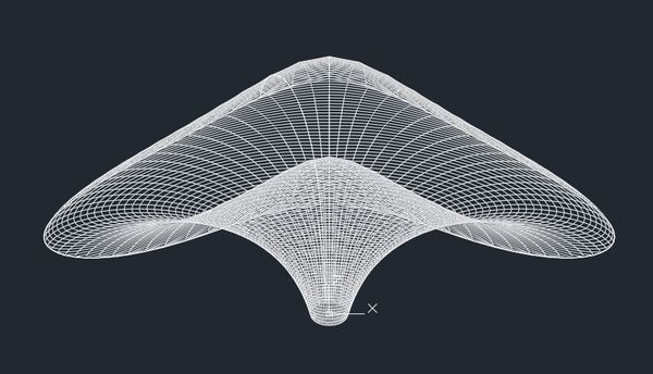
These two smooth profile horns inspired my work. Despite the often found diffration slots or throat discontinuities these horns show that it can work without such things:


The measurements were done near mouth slightly asymmetric. If the mic is placed to some greater distances we see of course the beaming effects and the transition is not as smooth as seen here.
The measurements were done near mouth slightly asymmetric. If the mic is placed to some greater distances we see of course the beaming effects and the transition is not as smooth as seen here.
If you have mesh files, why not do a few acoustic simulations (ABEC3) to verify the design before printing.
Yeah! Very good point! I simply do not know currently how to do that and my time went to 100% into the calculator. What do you need with mesh file - an STL?
Can this software simulate horns with bended mouth areas (which are not in the same plane)?
Last edited:
It's 3D BEM, so any design really.
The design file, in order of preference is [step, msh, stl]. I think providing just a design file should still protect your intellectual property (VBA).
If you're interested, post or PM, a simple design file and I can check its suitability.
The design file, in order of preference is [step, msh, stl]. I think providing just a design file should still protect your intellectual property (VBA).
If you're interested, post or PM, a simple design file and I can check its suitability.
Sure, very much appreciated!
But I would like to mention an important point. All the benefits that will ever come out of this project will be directed to organizations which support children that suffer for cancer - either research or for care and nursing. For every printed copy a donation has to be made. I will do the same. I currently have to think about how much is appropriate. Any suggestions?
Here is an STL with 425Hz construction vector:
View attachment DRBA_EP_425.zip
No problem, only two different settings in the sheet:
View attachment DRBA_EP_425s.zip
The coordinates are mm:
xamax ybmax zhmax zhmin
21.3mm 11.1mm 26.5mm 19.5mm
xa and yb are major and minor axis.
The transition from round to elliptical is a key factor. I used different functions for this and choosed the best looking. Let's see if everything was for the waste basket ;-)
Last edited:


With a selective laser sintering (The minimal quality IMHO) this part cost :This particular horn has 305mm depth, 516mm width and 256mm hight and without stereographic projection.
View attachment 740374
5246.47€ white
6482.90€ color
7472.05€ color + laquer
X2 if you need two of them, you must also raise the thickness of the part to be usable, it will increase the cost by a factor of x3 to x10 (you can also buy a lot of things with 140000€).
If i can help...
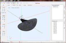
You have succeeded to use the R&D team software, you are a genius !
I'm unable to enter a list of very simple conical coordinates as you can see
https://www.casimages.com/i/190310090133127823.png.html
ABEC3 is a wonderful tool hampered by a lack of good tutorials. It requires alot of persistence to deduce how it works.
I'm still working on the sim. It's partially working. There is of course the subdomain problem with declaring where the mouth of the horn is. Usually it's regular geometry, but not for your horn
I'm very interested in modelling this complex interface boundary and still have several ideas to try, but they all take a little time. Patience.
Last edited:
- Home
- Loudspeakers
- Multi-Way
- Klangfilm spherical wave horn calculator - from round to elliptical