Hi,
I am needing some help with a pair of speakers I made about 20 years ago.
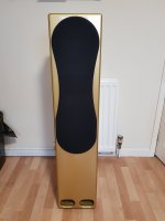
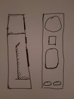
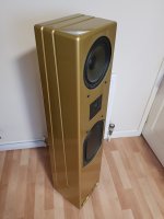
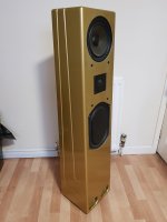
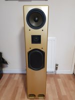
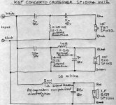
I designed them to keep the mid and the bass in separate spaces and giving the bass a resonating box inside which is then ported at the bottom. I have included a rough sketch in the photos.
Since then I have come to realise that I am not getting the best from them due to using the original 2 way crossover.
So from the begining...
I made these speakers using Celestion Ditton 110 top and mid/bass but added a Keff bass to the mix.
The crossover is the original 2 way Ditton and I added the Keff to this which means the Keff is getting low and mid frequency's.
I am thinking that as the crossover was made for the Dittons, I should keep it but potentially add another 2 way crossover in line to separate the low frequency for the Keff.
The specs for the Dittons are 8ohm, 60w, sensitivity 87.5db at 1w 1metre. They have a range of 78 to 20,000hz with the crossover crossing at 2300hz.
The Keff B139 SP1044 is 8ohm, 100w, sensitivity 87db at 1w 1metre with a range of 20 to 1000hz.
My idea, with my very limited knowledge, was to get a 2 way crossover, crossing at about 500hz to feed the Keff and to feed the Ditton crossover. This way, in my mind, the Dittons keep the right crossover and the Ditton mid/bass will be relieved of some of its lower duties.
My question is, am I looking at this the right way, is there a better or alternative way to get the best from these speakers and if not, where can I get a good pair of 2 way crossovers that will give the 20hz and crossover at about 500hz?
I would be grateful for any help on this...
I am needing some help with a pair of speakers I made about 20 years ago.
I designed them to keep the mid and the bass in separate spaces and giving the bass a resonating box inside which is then ported at the bottom. I have included a rough sketch in the photos.
Since then I have come to realise that I am not getting the best from them due to using the original 2 way crossover.
So from the begining...
I made these speakers using Celestion Ditton 110 top and mid/bass but added a Keff bass to the mix.
The crossover is the original 2 way Ditton and I added the Keff to this which means the Keff is getting low and mid frequency's.
I am thinking that as the crossover was made for the Dittons, I should keep it but potentially add another 2 way crossover in line to separate the low frequency for the Keff.
The specs for the Dittons are 8ohm, 60w, sensitivity 87.5db at 1w 1metre. They have a range of 78 to 20,000hz with the crossover crossing at 2300hz.
The Keff B139 SP1044 is 8ohm, 100w, sensitivity 87db at 1w 1metre with a range of 20 to 1000hz.
My idea, with my very limited knowledge, was to get a 2 way crossover, crossing at about 500hz to feed the Keff and to feed the Ditton crossover. This way, in my mind, the Dittons keep the right crossover and the Ditton mid/bass will be relieved of some of its lower duties.
My question is, am I looking at this the right way, is there a better or alternative way to get the best from these speakers and if not, where can I get a good pair of 2 way crossovers that will give the 20hz and crossover at about 500hz?
I would be grateful for any help on this...
Attachments
one of the simplest ways to deal with this is to make the B139 a .5 woofer, crossing over at the baffle step frequency, by adding an inductor in series. Baffle step freq is 115/baffle width in metres, find the impedance of the B139 at that frequency, and calculate the appropriate inductor (or use an on line calculator). The inductor/B139 in series are connected to the input terminals of the speaker.
There are impedance plots here, but apparently there are different versions of the B139...:
KEF B139b sp1044
There are impedance plots here, but apparently there are different versions of the B139...:
KEF B139b sp1044
Thank you for the reply...
I'm not sure what the calculations are about or how to do them but with my limited knowledge am I understanding that I just need to put something in line with the Keff (I'm pretty sure this is the original Keff, not the remake) and drive the Keff straight from the terminals?
So does this mean the mid is still doing the bass as well?
I suppose a 2.5 way is doable, but even that simplistic approach would need a redesign of the Celestion part of the filter to lighten bass duties for the 6" to confer any real advantage. Not trivial. The levels would change in the core two way part of the project.
A pure three way works like this:
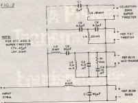
The sort of filter that might be a start for you is below. A 6" paper mid is not the same at all as a KEF B110 5" polycone driver. I think you'll need attenuation on the 6" mid and tweeter, and possibly impedance correction. Quite a redesign, and a simple mid doesn't have the big bafflestep coil that you use in a two way.
I'm sure it's doable with a bit of trial and error, but I don't have the time here.
You'd need to model it in some way, because a 6" mid isn't very commonly done.
Software | Visaton
These projects can be imported into the projekte file of Boxsim and fiddled with, including substituting drivers:
3 Wege – Boxsim Projektdatenbank
A pure three way works like this:
The sort of filter that might be a start for you is below. A 6" paper mid is not the same at all as a KEF B110 5" polycone driver. I think you'll need attenuation on the 6" mid and tweeter, and possibly impedance correction. Quite a redesign, and a simple mid doesn't have the big bafflestep coil that you use in a two way.
I'm sure it's doable with a bit of trial and error, but I don't have the time here.
You'd need to model it in some way, because a 6" mid isn't very commonly done.
Software | Visaton
These projects can be imported into the projekte file of Boxsim and fiddled with, including substituting drivers:
3 Wege – Boxsim Projektdatenbank
Attachments
Last edited:
A 3mH inductor (coil) wired in series between the positive input terminal and the B139 will roll it off at around 500Hz. This is a simple (but worthy) first port of call.Thank you for the reply...
I'm not sure what the calculations are about or how to do them but with my limited knowledge am I understanding that I just need to put something in line with the Keff and drive the Keff straight from the terminals?
So does this mean the mid is still doing the bass as well?
However, this does mean that the mid will still be sharing bass duties.
3.00mH Ferrite Inductor
P.S. I recommend you roll the B139 off at a lower frequency to reduce overlap with the mid/bass driver. A 7mH inductor will act around 250Hz.
7.00mH Ferrite Inductor
7.00mH Ferrite Inductor
Re:'need a redesign of the Celestion part of the filter to lighten bass duties" - surely the closed box takes care of that, at least in part??
some guesswork: the B129 is 210mm wide, so your cab is ~250mm across? - that gives a baffle step freq of 115/.25 = 460Hz.
At that frequency the Z of the driver won't be much above Re, Zmin is quoted as 6.7 on the data sheet, so plugging these numbers into a calculator will give an inductor of 2.3mH. you may wish to crossover lower as suggested by Galu, the next sized up inductor would usually be 2.5mH for an xover freq of ~420 Hz.
Personally I'd probably go for ~3mH (Xover freq ~350Hz), but it's really up to personal taste.
Use a ferrite cored inductor with the lowest possible DC resistance to minimise power loss to the woofer.
The naysayers will now pipe up & tell you that Ferrite core inductors cause hyterisis distortion, and they do, but only if you run them at PA levels, they're ok if you want to keep your hearing....
Hi Pete!
I see we're pretty much in agreement (I calculated for Z = 10 ohm after looking at the impedance plots to which you referred in post #2).
I also considered a series capacitor in front of the original 2-way crossover, but like you I am uncertain of the interaction.
Perhaps Steve will comment on whether this is doable.
However, if John is willing to experiment, he could match your 3mH inductor with a non polar capacitor of value 68uF.
68 fd ECap100 Electrolytic Capacitor

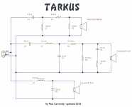
Adding a couple of electrolytic capacitors is cheap entertainment. Here's what I was trying to recall as a goodish idea, and it's all about the right idea IMO, the Tarkus by Paul Carmody:
Tarkus - undefinition
Big mid 3-ways are rare. This one pulls it off because of the attenuation on the 6.5" mid which acts as impedance correction, and makes a difficult speaker easier. The actual crossover point between bass and mid is adjustable. So something on these lines with a 5mH and 47uF bass filter or whatever we go for based on the KEF B139 bass unit ideas. The mid to tweeter crossover point is 2.3kHz in the Celestion Ditton 110, so we are in the right ballpark.

This is a big project for the inexperienced. But really the only way to fix this, IMO.
A good start would be measuring driver DC resistances with a mutimeter, and dissecting the Celestion crossover to see what is reuseable. This could actually be a very fine speaker and worth the effort.
Tarkus - undefinition
Big mid 3-ways are rare. This one pulls it off because of the attenuation on the 6.5" mid which acts as impedance correction, and makes a difficult speaker easier. The actual crossover point between bass and mid is adjustable. So something on these lines with a 5mH and 47uF bass filter or whatever we go for based on the KEF B139 bass unit ideas. The mid to tweeter crossover point is 2.3kHz in the Celestion Ditton 110, so we are in the right ballpark.
This is a big project for the inexperienced. But really the only way to fix this, IMO.
A good start would be measuring driver DC resistances with a mutimeter, and dissecting the Celestion crossover to see what is reuseable. This could actually be a very fine speaker and worth the effort.
Last edited:
Of course I want the best from these speakers which is why I am asking you guys for advice.
My knowledge in this area is almost none which puts me an an awkward position.
If it was a case of getting a pair of crossovers made at certain frequencies, that for me is doable, if it is a case of soldering some electrolytic capacitors in line, this for me is also doable.
Although I don't fully understand your post Steve, it seems that this could be the way to go for the best result. My question is, as this is beyond my capabilities, are there people that can do this for me?
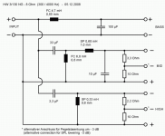
I haven't really given this much thought, but some off-the-shelf crossovers are in the right ballpark:
HW 3/130 NG - 8 Ohm | Visaton
Not a million miles away from where you want to be!
Falcon Acoustics do some KEF and Cambridge crossovers too:
https://www.falconacoustics.co.uk/crossovers-ls35a-networks-filters-falcon.html
Now do those measurements and simulating I asked for. The Visaton W200S, W170S and G20SC drivers will be similar for simming purposes. This is serious engineering, not messing about. I will help you up to a point, but it's your project.
Attachments
Steve, I am going to try and do this. The Tarkus is a great example and I know what I have is also a great speaker. I already love the sound of these but know it can be improved with the right attention. The current crossover configuration just doesn't sit right with me and hasn't for a while.
I am borrowing a multimeter tomorrow to do the measurements and will load the SIM program on the laptop and see if I can work it.
I will let you know how I get on...
Kind regards,
John.
I am borrowing a multimeter tomorrow to do the measurements and will load the SIM program on the laptop and see if I can work it.
I will let you know how I get on...
Kind regards,
John.
The 139 looks like a sub to me - it looks like it might be best crossed lower than 500Hz. A search seems to confirm my suspicion:
I personally don't like difficult passive crossovers, so I'd probably go with the option I underlined.
What are your capabilities? What's your budget (time and money)? What is the rest of your system?
One way to minimise the spend (in time and money) and sidestep all the difficut passive stuff is to not do any of it. Going active can be cheaper and easier.
e.g. you could leave the Ditton crossover in place, and simply run the B139s from another amp that's built for situations like this. This one is on special right now.
"A built-in, switchable low-pass filter also makes the IA150 a superb subwoofer amp!"
Franklin Audio IA150 150W Power Amplifier
the B139 has a really bad break up mode
(around 1K I recollect) which makes it difficult to use in a 3-way
design with a simple crossover crossing over to a mid unit.
Consequently its more sensible (if they are in good condition)
to use the B139s for a powered subwoofer or stereo subs.
I personally don't like difficult passive crossovers, so I'd probably go with the option I underlined.
Although I don't fully understand your post Steve, it seems that this could be the way to go for the best result. My question is, as this is beyond my capabilities, are there people that can do this for me?
What are your capabilities? What's your budget (time and money)? What is the rest of your system?
One way to minimise the spend (in time and money) and sidestep all the difficut passive stuff is to not do any of it. Going active can be cheaper and easier.
e.g. you could leave the Ditton crossover in place, and simply run the B139s from another amp that's built for situations like this. This one is on special right now.
"A built-in, switchable low-pass filter also makes the IA150 a superb subwoofer amp!"
Franklin Audio IA150 150W Power Amplifier
Last edited:
The 139 looks like a sub to me - it looks like it might be best crossed lower than 500Hz. A search seems to confirm my suspicion:
I personally don't like difficult passive crossovers, so I'd probably go with the option I underlined.
What are your capabilities? What's your budget (time and money)? What is the rest of your system?
One way to minimise the spend (in time and money) and sidestep all the difficut passive stuff is to not do any of it. Going active can be cheaper and easier.
e.g. you could leave the Ditton crossover in place, and simply run the B139s from another amp that's built for situations like this. This one is on special right now.
"A built-in, switchable low-pass filter also makes the IA150 a superb subwoofer amp!"
Franklin Audio IA150 150W Power Amplifier
My capabilities are that I can do some soldering if following instructions but don't really understand the terminology or what the components are about.
Budget would hopefully not exceed £200, time is not limited apart from around normal working hours.
I am running the speakers from a Nad C370.
So my question is, is there much of a difference with your suggestion and just putting a passive low pass filter in line with the Keff?_
John, why not try the low pass filter first? It's such a cheap and easy modification, and is easily reversible.
I'd go for the 7mH option to roll off more of the high frequencies.
Then take time to research the topic of loudspeaker crossovers so that you can understand the function of the circuits which Steve will be suggesting.
I'd go for the 7mH option to roll off more of the high frequencies.
Then take time to research the topic of loudspeaker crossovers so that you can understand the function of the circuits which Steve will be suggesting.
- Status
- This old topic is closed. If you want to reopen this topic, contact a moderator using the "Report Post" button.
- Home
- Loudspeakers
- Multi-Way
- Help needed for home made