Hi all,
Been toying with this idea for a while - I like the concept of the Duevel Planets omni speakers and wanted to have a go building some, but I want to add a transmission line to the woofer in the cabinet in order to get good bass response without having to use a separate sub woofer.
Only thing ive decided on so far is to use the Beocreate as the amp - Beocreate 4 channel amplifier | HiFiBerry - It has 180W (2x30W and 2x60W) outputs so this will be the deciding factor (i think?) for driver selection. Planning on not using physical cross overs, bi amping, and using the DSP for crossover and room correction.
Woofer: Dayton Audio DSA175-8 6-1/2" Designer Series Aluminum Cone Woofer
Tweeter: Dayton Audio DC28F-8 1-1/8" Silk Dome Tweeter
Not sure if those drivers are a good choice or not, perhaps someone can chime in. I thought perhaps they would work well with the power level of the amp but not sure. Wanted to use a slightly larger woofer in order to bring bass response down to the lower freqs (the original Planets use a 5 inch).
I did some basic calculations using an online calculator - quater wavelength is 1.344m using a tapered line and i did some basic cad stuff which showed i could fit this line (twice folded) with a linear taper inside a cabinet that was 560mm tall, 200mm deep and 400mm wide.
Background info - i've never built a speaker cabinet before but have an electrical background, and ive got access to a CNC and have done a lot of work with mdf/ply, so the building isnt a problem, just the design.
I work in a company that does RF (radio frequency) design, and a colleague with years of experience in RF transmission line design can help me with the phasing/tuning/impedance matching (the principals are the same).
Any suggestions would really help! looking to decide on a woofer and tweeter combo, so i can work forward from there.
Thanks in advance!
UPDATE 28/11/18
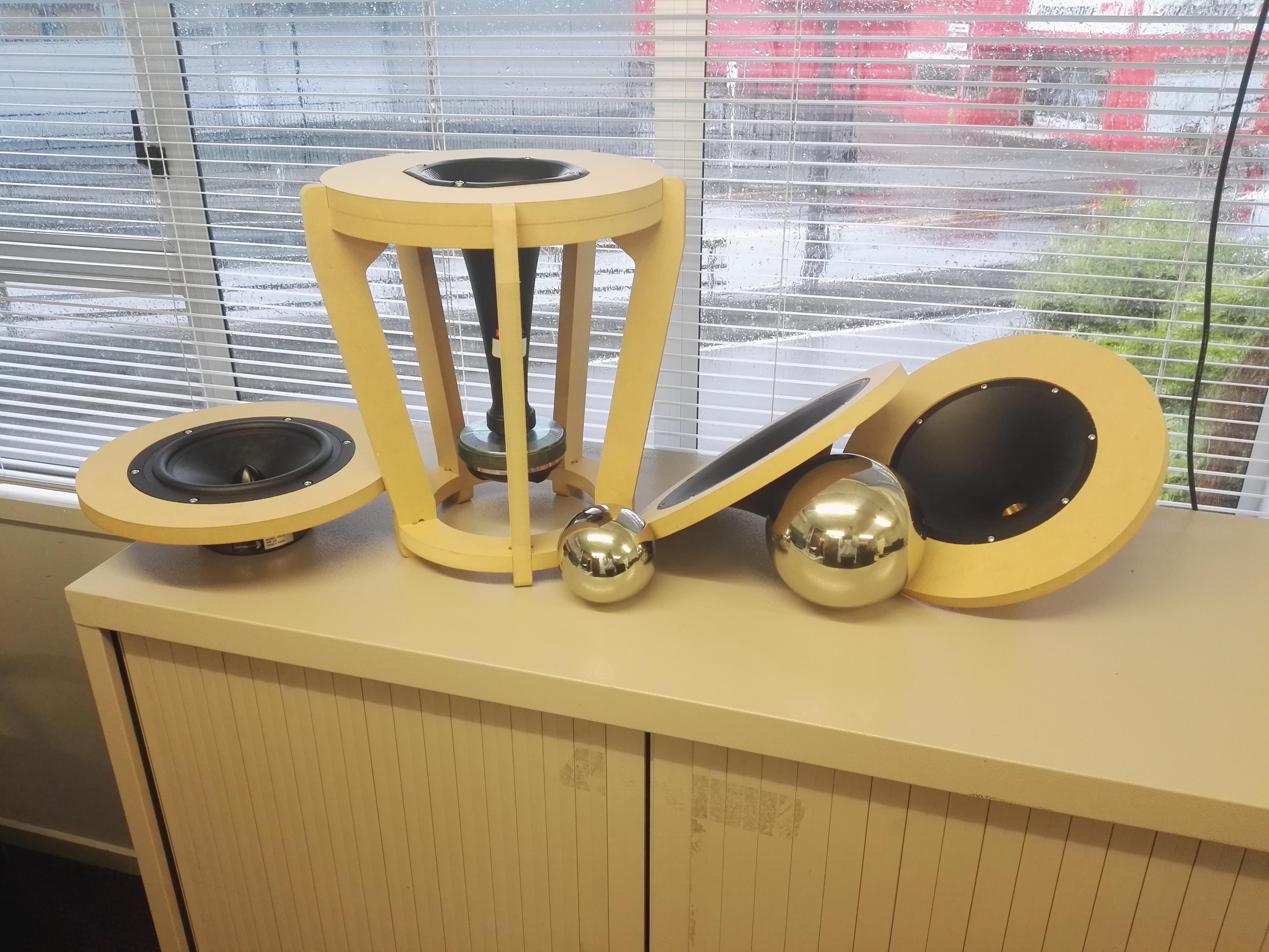
Decided on the parts to use and have ordered them, everything has arrived;
- Dayton RS225PA-4 Woofer
- Selenium D220Ti compression driver
- Bunch of horns to test
- Dayton usb calibration mic
- Beocreate board plus raspberry pi
UPDATE 14/01/19
- Have made up test stands for the woofer and horns (photo attached)
- Currently setting up software etc on the DSP and will start testing when that's done
Will do some more updates here when there is news
Been toying with this idea for a while - I like the concept of the Duevel Planets omni speakers and wanted to have a go building some, but I want to add a transmission line to the woofer in the cabinet in order to get good bass response without having to use a separate sub woofer.
Only thing ive decided on so far is to use the Beocreate as the amp - Beocreate 4 channel amplifier | HiFiBerry - It has 180W (2x30W and 2x60W) outputs so this will be the deciding factor (i think?) for driver selection. Planning on not using physical cross overs, bi amping, and using the DSP for crossover and room correction.
Woofer: Dayton Audio DSA175-8 6-1/2" Designer Series Aluminum Cone Woofer
Tweeter: Dayton Audio DC28F-8 1-1/8" Silk Dome Tweeter
Not sure if those drivers are a good choice or not, perhaps someone can chime in. I thought perhaps they would work well with the power level of the amp but not sure. Wanted to use a slightly larger woofer in order to bring bass response down to the lower freqs (the original Planets use a 5 inch).
I did some basic calculations using an online calculator - quater wavelength is 1.344m using a tapered line and i did some basic cad stuff which showed i could fit this line (twice folded) with a linear taper inside a cabinet that was 560mm tall, 200mm deep and 400mm wide.
Background info - i've never built a speaker cabinet before but have an electrical background, and ive got access to a CNC and have done a lot of work with mdf/ply, so the building isnt a problem, just the design.
I work in a company that does RF (radio frequency) design, and a colleague with years of experience in RF transmission line design can help me with the phasing/tuning/impedance matching (the principals are the same).
Any suggestions would really help! looking to decide on a woofer and tweeter combo, so i can work forward from there.
Thanks in advance!
UPDATE 28/11/18
Decided on the parts to use and have ordered them, everything has arrived;
- Dayton RS225PA-4 Woofer
- Selenium D220Ti compression driver
- Bunch of horns to test
- Dayton usb calibration mic
- Beocreate board plus raspberry pi
UPDATE 14/01/19
- Have made up test stands for the woofer and horns (photo attached)
- Currently setting up software etc on the DSP and will start testing when that's done
Will do some more updates here when there is news
Last edited:
The DSA175-8 published specs show an fs of 38 Hz and a Qts of 0.29. If you chose your line's length and taper to achieve a 1/4-wavelength resonant frequency equal to fs, you won't achieve what you're hoping for; the line's 1/4-wave resonance will need to be appreciably higher than fs because its Qts is so low. Is 1.344 meters the actual proposed length? What taper ratio did you choose? What f3 are you hoping to achieve? Note that once you have a tuning frequency appropriate for the driver's fs and Qts, the bass response (f3) will then be determined by the volume in the line.
Paul
Paul
Hi all,
Been toying with this idea for a while - I like the concept of the Duevel Planets omni speakers and wanted to have a go building some, but I want to add a transmission line to the woofer in the cabinet in order to get good bass response without having to use a separate sub woofer.
Only thing ive decided on so far is to use the Beocreate as the amp - Beocreate 4 channel amplifier | HiFiBerry - It has 180W (2x30W and 2x60W) outputs so this will be the deciding factor (i think?) for driver selection. Planning on not using physical cross overs, bi amping, and using the DSP for crossover and room correction.
Woofer: Dayton Audio DSA175-8 6-1/2" Designer Series Aluminum Cone Woofer
Tweeter: Dayton Audio DC28F-8 1-1/8" Silk Dome Tweeter
Not sure if those drivers are a good choice or not, perhaps someone can chime in. I thought perhaps they would work well with the power level of the amp but not sure. Wanted to use a slightly larger woofer in order to bring bass response down to the lower freqs (the original Planets use a 5 inch).
I did some basic calculations using an online calculator - quater wavelength is 1.344m using a tapered line and i did some basic cad stuff which showed i could fit this line (twice folded) with a linear taper inside a cabinet that was 560mm tall, 200mm deep and 400mm wide.
Background info - i've never built a speaker cabinet before but have an electrical background, and ive got access to a CNC and have done a lot of work with mdf/ply, so the building isnt a problem, just the design.
I work in a company that does RF (radio frequency) design, and a colleague with years of experience in RF transmission line design can help me with the phasing/tuning/impedance matching (the principals are the same).
Any suggestions would really help! looking to decide on a woofer and tweeter combo, so i can work forward from there.
Thanks in advance!
Some random observations:
1) In a conventional loudspeaker, the tweeter has a beamwidth of about 180 degrees above 2khz, and then above 10khz that beam narrows to about sixty degrees. Because the beam is relatively narrow, the tweeter doesn't have to work as hard. In a omnipolar speaker, like the Duevel, the tweeter radiates into 360 degrees. This puts a TREMENDOUS strain on the tweeter; it has to work about twice as hard. This is likely why Duevel uses a compression driver.
2) B&O achieves similar results using acoustic lens technology licensed for Sausalito Audio Works. I've built a zillion of these, they're fun. I've posted a bunch of threads on that, it might be worth a look. Check out the Beolab 5.
If I were building the speaker that you describe, I'd look at a couple of drivers that can take some serious power. Omni speakers are power hungry. B&C 8NDL51 for the bass and a compression driver for the highs would be a good place to start. The compression drivers from JBL and Eminence are affordable and well suited to this application because the diaphragm is a ring. A ring radiator is well suited to omni designs.
The DSA175-8 published specs show an fs of 38 Hz and a Qts of 0.29. If you chose your line's length and taper to achieve a 1/4-wavelength resonant frequency equal to fs, you won't achieve what you're hoping for; the line's 1/4-wave resonance will need to be appreciably higher than fs because its Qts is so low. Is 1.344 meters the actual proposed length? What taper ratio did you choose? What f3 are you hoping to achieve? Note that once you have a tuning frequency appropriate for the driver's fs and Qts, the bass response (f3) will then be determined by the volume in the line.
Paul
I used a speadsheet calculator (Kings i think - will find it) and then the calc also suggested a 0.1 taper ratio, so using that ratio and plugging in the numbers it gave me 1.344m. was just a first calculation, i'll look more once ive selected an appropriate driver.
Makes sense! Ok so i'll start looking for a more efficient and sensitive tweeter for this application. Would a planar tweeter be of any use? or best to go with a horn loaded tweeter?1) In a conventional loudspeaker, the tweeter has a beamwidth of about 180 degrees above 2khz, and then above 10khz that beam narrows to about sixty degrees. Because the beam is relatively narrow, the tweeter doesn't have to work as hard. In a omnipolar speaker, like the Duevel, the tweeter radiates into 360 degrees. This puts a TREMENDOUS strain on the tweeter; it has to work about twice as hard. This is likely why Duevel uses a compression driver.
Had a look at the Beolab 5, looks awesome! Not sure how i'd create that though? I have a 3D printer, but not really a fan. I found the stainless spheres of the planets at low cost, so that was easier for me, but open to other ideas. Ideally trying to keep cost low.2) B&O achieves similar results using acoustic lens technology licensed for Sausalito Audio Works. I've built a zillion of these, they're fun. I've posted a bunch of threads on that, it might be worth a look. Check out the Beolab 5.
If I were building the speaker that you describe, I'd look at a couple of drivers that can take some serious power. Omni speakers are power hungry. B&C 8NDL51 for the bass and a compression driver for the highs would be a good place to start. The compression drivers from JBL and Eminence are affordable and well suited to this application because the diaphragm is a ring. A ring radiator is well suited to omni designs.
With the drivers, I'd still very much like to stick with using the Beocreate amp which limits me to about 60W for the main woofers. I'll look for some more sensitive woofers perhaps to solve that. Would the increase in sensitivity (theoretically) from the transmission line make up somewhat for the lower efficiency of the omni design?
Thanks again!
I use only Martin King's modeling software (not his spread sheet calculator) for designing TLs and out of curiosity modeled a tapered TL using the published specs for the DSA175. With a taper ratio of 0.1 (which I call a 10:1 because the area of the line reduces by a factor of 10:1 going from the closed end to the open end) the line's actual length that results in a nominally flat response came out to be 0.76 meters long (30 inches). The line's 1/4-wavelength resonant frequency was 60 Hz with the line unstuffed, and became ~53 Hz with the first 2/3 of the line's length stuffed at a density of 0.75 lb/ft3. A line that's 1.3 meters long and tapered at 10:1 will not create a 1/4-wavelength resonant frequency appropriate for this driver's fs and low Qts. I arbitrarily ended up with a line volume of 20 liters, resulting in an f3 of just over 50 Hz.
Paul
Paul
I used a speadsheet calculator (Kings i think - will find it) and then the calc also suggested a 0.1 taper ratio, so using that ratio and plugging in the numbers it gave me 1.344m. was just a first calculation, i'll look more once ive selected an appropriate driver.
I use only Martin King's modeling software (not his spread sheet calculator) for designing TLs and out of curiosity modeled a tapered TL using the published specs for the DSA175. With a taper ratio of 0.1 (which I call a 10:1 because the area of the line reduces by a factor of 10:1 going from the closed end to the open end) the line's actual length that results in a nominally flat response came out to be 0.76 meters long (30 inches). The line's 1/4-wavelength resonant frequency was 60 Hz with the line unstuffed, and became ~53 Hz with the first 2/3 of the line's length stuffed at a density of 0.75 lb/ft3. A line that's 1.3 meters long and tapered at 10:1 will not create a 1/4-wavelength resonant frequency appropriate for this driver's fs and low Qts. I arbitrarily ended up with a line volume of 20 liters, resulting in an f3 of just over 50 Hz.
Paul
I used a speadsheet calculator (Kings i think - will find it) and then the calc also suggested a 0.1 taper ratio, so using that ratio and plugging in the numbers it gave me 1.344m. was just a first calculation, i'll look more once ive selected an appropriate driver.
Thanks so much for this, starting to make more sense.
Ok so ideally i'd want a f3 around the 30Hz mark i think, but im not sure what's reasonable or achievable given the constraints.
And i understand now that a TL favors a higher Qts driver. Would this suit? Aurum Cantus AC-180F1D 7" DVC Woofer
It has a Qts of 0.59. Seems to be ok on paper but again i'm not so experienced with this stuff. I do notice as well the sensitivity is lower (87db). What sort of sensitivity should i be aiming for?
And theoretically what id the ideal Qts for such a driver in a TL?
Thanks!
A driver with a high Qts can also be problematic in a TL; I get best results with drivers having a Qts in the range of 0.35 to 0.5. Whether or not you can comfortably achieve an f3 with a given driver depends on several factors. Once you determine an optimal system tuning frequency that gives an overall flat response, f3 will be determined by the volume in the line, and the driver's Xmax will determine how loud it can play when reaching f3. Regarding the Aurum Cantus driver you mentioned, their published specs are generally not very reliable and for any driver you choose, you either need to measure their T/S values yourself or use those measured by someone else that can be trusted.
Paul
Thanks so much for this, starting to make more sense.
Ok so ideally i'd want a f3 around the 30Hz mark i think, but im not sure what's reasonable or achievable given the constraints.
And i understand now that a TL favors a higher Qts driver. Would this suit? Aurum Cantus AC-180F1D 7" DVC Woofer
It has a Qts of 0.59. Seems to be ok on paper but again i'm not so experienced with this stuff. I do notice as well the sensitivity is lower (87db). What sort of sensitivity should i be aiming for?
And theoretically what id the ideal Qts for such a driver in a TL?
Thanks![/QUOTE]
The HF will be the issue, as already pointed out. The sensitivity will also be low because you're driving 360deg and you need a suitable room for it.
I have tried a few different methods and shapes to get an omni dispersion pattern. A radial horn with compression driver, like the other Duevels (not planets), works well. I could not get a good pattern from a dome tweeter using any shape above it.
There may be some tests of interest to you at this link OmniDirectional - work in progress It eventually turns into a working Omni after several attempts and I enjoy listening to them.
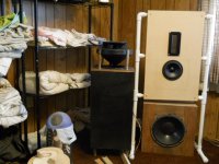
I experienced what others have stated here. The tweeter was running out of gas in the Duevel arrangement. I decided to marry the Duevel and acoustics lens - think Beolab 50. Here is a pic of the project still in progress. I need to complete the crossover. I really do enjoy the omni mid-range.
Attachments
The HF will be the issue, as already pointed out. The sensitivity will also be low because you're driving 360deg and you need a suitable room for it.
I have tried a few different methods and shapes to get an omni dispersion pattern. A radial horn with compression driver, like the other Duevels (not planets), works well. I could not get a good pattern from a dome tweeter using any shape above it.
There may be some tests of interest to you at this link OmniDirectional - work in progress It eventually turns into a working Omni after several attempts and I enjoy listening to them.
Thanks for all the helpful info.
Understood about the tweeter/high frequency efficiency problem.
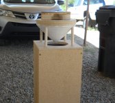
I would be happy to use a compression driver fed into a horn, and then still use a sphere for dispersion - would this work ok? I was looking and it doesnt seem too hard to find a compression driver that will do 110db ish sensitivity (on paper at least), when matched to the correct horn.
From what i understand, this is the arrangement of the Planets? I also saw the reflector used on the Enterprise and this looks like it could be more effective, but the general arrangement is still the same.
Thanks!
It certainly looks like a CD and a waveguide that's under the sphere/reflector. That's definitely better than a dome tweeter for this application. I tried lots of shape adjustments through ABEC models. I'll check if I kept some relevant spherical ones. I would suspect that a smallish sphere would still allow most the MF-HF waves to wrap around and continue in the same direction to diffuse off the ceiling.
To get the wavefront to exit perpendicular to the driver I needed physical boundaries (inner and outer walls). So I ended up with nested waveguides like the Duevel Bella Luna. I also found that, at higher freq I would get reflections from anything above the driver, so I have a narrow pointy tip above the CD to reduce this. The cone above the woofer in my Omni helps direct MF and reduce the MF reflections because I XO@1800Hz.
The basis (sim & calc) for what I did is at this post OmniDirectional - work in progress and the subsequent post.
Thanks for the response.
I had a look through your thread, the ABEC software looks interesting, will give it a go.
Had another question - What would be the best way to measure the phase inside the TL for tuning purposes?
I assume I could get a usb audio interface (focusrite or similar) and plug in twin measurement mics, one at the driver cone and another at the exit of the TL port, and analyse using REM? Again, no idea as i've never done this before.
At work we use a vector network analyzer (VNA) to tune RF antennas, so im curious as to what the acoustic equivalent is. Will start a new thread with the measurement question, but thought i'd post here as well.
Thanks!
You should only need a single mic and REW to measure the phase. REW will align to its swept sine and you can extract phase (unwrap and generate min phase) for near field measurements of both driver and port exit.
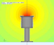
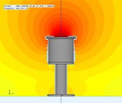
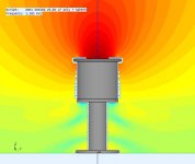
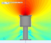
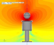
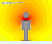
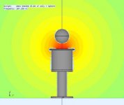
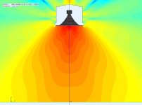
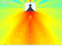
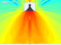
I could not find all the older trial reflector shapes I tried. So I just removed the top of my Omni ABEC model and added a sphere based on the Planet's images. I used my 8" Silverflute whereas the Planet has a 6" so I scaled the sphere to match. This should give a good idea of what happens.
I'm going to post the result images in 2 separate posts so that the unobstructed woofer is viewed over top of the sphere images. You can see the woofer starting to beam and narrow.
Attachments
Thanks so much for this! Helps explain things a lot.
I see you still tend to get the upper lobe with the sphere. Will have a play around and talk to the other engineer.
Seems like a sphere is not the greatest reflector, but they are so easy to get hold of compared to fabricating a more ideal shape.
I see you still tend to get the upper lobe with the sphere. Will have a play around and talk to the other engineer.
Seems like a sphere is not the greatest reflector, but they are so easy to get hold of compared to fabricating a more ideal shape.
That's very true, spheres are easy to get.
Yes, its not ideal, but it could still work for a woofer with a reasonably low XO (<2Khz) and high order filter (4th order). In the images above, the last pic has the woofer dia, sphere dia and freq wavelength about equal.
The more difficult problem is the HF. If I get some spare cycles I'll post a sphere in front of a short waveguide like the Planets. I don't remember trying that combo in my earlier attempts. It might not be ideal but maybe workable in order for you to try an Omni.
Last edited:
I tried ABEC, quite the learning curve haha, but i'll stick at it.
And looking for other things I can use as reflectors but nothing i can find with a hyperbolic shape in the correct size that is readily available.
I think it might just be easier to 3D print if i wanted to go down that route. I was thinking i could possibly 3D print an OK ish hyperbolic cone with a shaft attachment, and then smooth out the shape on a lathe and polish it off
Duevel Bella Luna - Weibchen CNC
Just saw this as well, didn't realise that was how they made them (I thought they were turned).
I have access to a 3 axis CNC that is more than capable of this, but the toolpath programming would be a pain.
Would this horn design be significantly better for high frequency performance? I know its all subjective, but just wondering whether its worth it or not.
Thanks!
ABEC is a very steep climb and desperately needs better tutorials & help & error parsing to understand what its doing. It's an amazing tool and I'm still learning it.
Yeah, I would have thought lathe then a CNC touch up. Good video though, and this other one is of the inner shape that forms the radial horn Duevel Bella Luna - male CNC
I do think its more effective to have inner/outer surfaces for the HF to direct the wavefront. You can get close by nesting 2 circular horns like the Dayton 8 or 10" models and add a tip to the inner one. I did find the spacing and tip shape did make a difference. I still need to post a horn + sphere,.. probably later today.
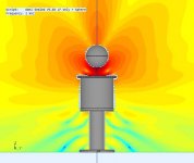
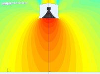
Sooner than expected. It seems I had some partial work when I was playing with the HF sections. So it was easy to drop a sphere in front. I use a 10" Dayton circular model which is larger than the Planet, so I scaled the sphere dia and offset just to get a picture of whats happening.
Again, 2 posts so you can compare top and bottom.
Again, 2 posts so you can compare top and bottom.
Attachments
- Home
- Loudspeakers
- Multi-Way
- Transmission line Omni speakers? Duevel Planets clone with transmission line?