I'm mostly a car audio guy so please bear with my lack of knowledge on some of these topics. I've got a pair of 6" Silver Flute drivers mounted in my doors and decided to build some AP type enclosures for them to see how they'd work. There's not a lot of AP guidance available on the internet, other than one site that states that:
"..the woofer's Qts (total system Q) that determines the AP candidates! ANY WOOFER WITH A QTS OF .45 or LESS CAN WORK VERY WELL IN AP DESIGNS! I made that bold so it will stick with you guys. So, if you want to try your hand at this type of enclosure, seek the Qts spec of the woofer. If it is less than or = to .45, you have a winner. You will find that it is mainly the subs designed for ported enclosures"
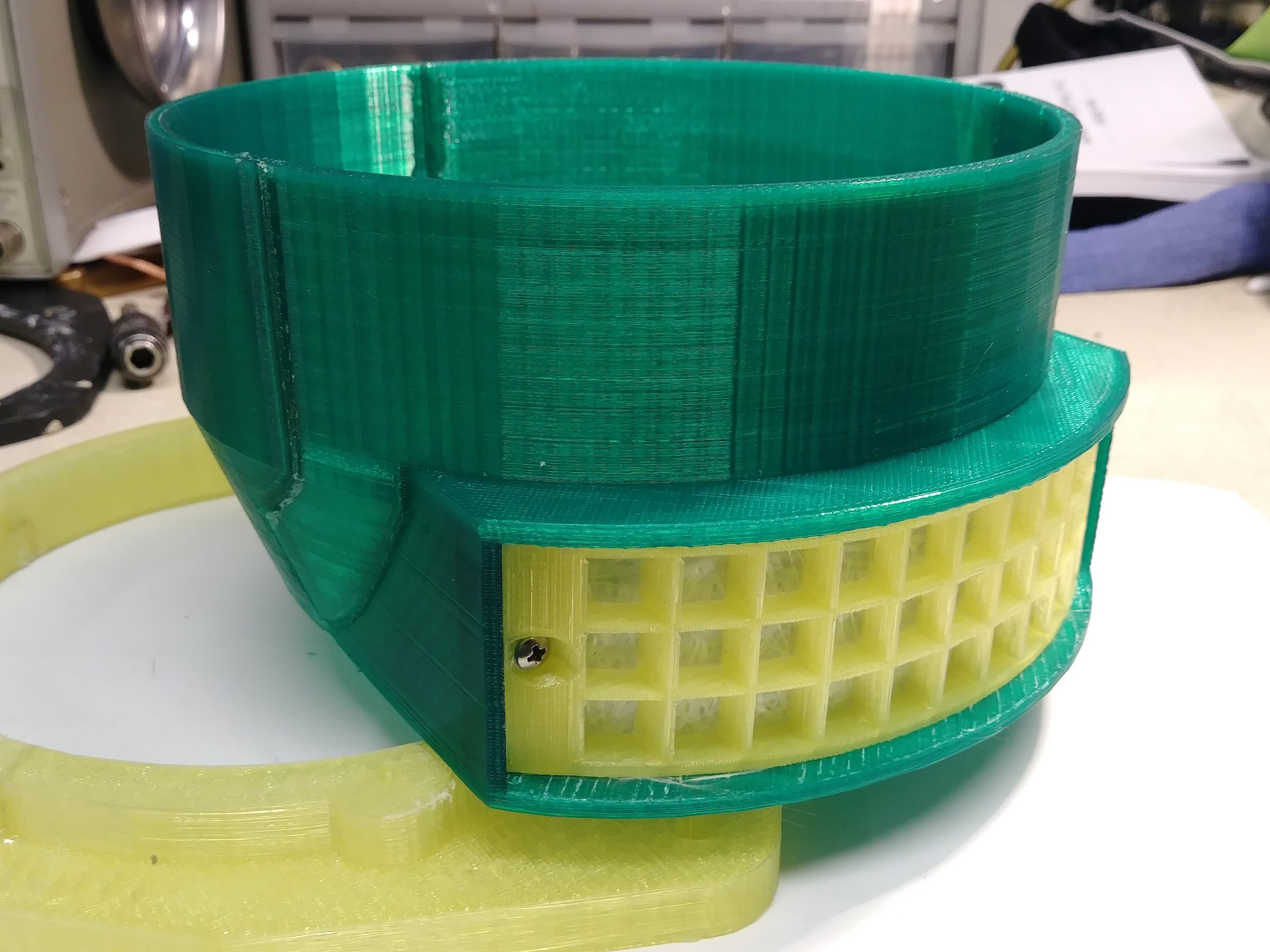
The 6" Silver Flute has a published Qts of 0.24, and Zaph's testing showed 0.29. Based on the criteria above it seemed like a good candidate for an AP enclosure. There's not a lot of space in a car door, so the enclosure depth was limited, and it also had to be water resistant, so the port had to be shrouded and point down. The membrane is fiberglass matte, in layers, and clamped between two grilles. Here's what it looks like:
So I ran some tests using REW and my living room floor, to get a rough idea of the change in the impedance curve with varying amounts of fiberglass membrane. The tests were run in the middle of the floor with the driver in the enclosure and aimed up at the ceiling. It wasn't extremely precise, in that I was holding the test mic at approximately the same height over the driver in each test. I can see that adding more resistance to the membrane drops the low frequency impedance spike, but from what I understand that in itself isn't really critical unless using tube amps? I'm using all Class D in the car. Anyway the results of the impedance tests came out about as expected:
It's also altering the frequency response of the driver, but that's not critical in my application either, as I have a DSP and can work with just about anything. Here's the amplitude plots:
But the real questions come from the distortion runs. It seems that the AP membrane reduces the measured distortion levels by as much as 5 dB up to about 2000 Hz, then there's some real nastiness that wasn't in the open vent plot. Maybe that's from reflections inside the enclosure? But overall below 2000 Hz why would the distortion drop so much with an AP membrane in place?
So, ultimately I'm trying to figure out what I figured out, and if I should bother applying it. Thanks -
"..the woofer's Qts (total system Q) that determines the AP candidates! ANY WOOFER WITH A QTS OF .45 or LESS CAN WORK VERY WELL IN AP DESIGNS! I made that bold so it will stick with you guys. So, if you want to try your hand at this type of enclosure, seek the Qts spec of the woofer. If it is less than or = to .45, you have a winner. You will find that it is mainly the subs designed for ported enclosures"
The 6" Silver Flute has a published Qts of 0.24, and Zaph's testing showed 0.29. Based on the criteria above it seemed like a good candidate for an AP enclosure. There's not a lot of space in a car door, so the enclosure depth was limited, and it also had to be water resistant, so the port had to be shrouded and point down. The membrane is fiberglass matte, in layers, and clamped between two grilles. Here's what it looks like:
So I ran some tests using REW and my living room floor, to get a rough idea of the change in the impedance curve with varying amounts of fiberglass membrane. The tests were run in the middle of the floor with the driver in the enclosure and aimed up at the ceiling. It wasn't extremely precise, in that I was holding the test mic at approximately the same height over the driver in each test. I can see that adding more resistance to the membrane drops the low frequency impedance spike, but from what I understand that in itself isn't really critical unless using tube amps? I'm using all Class D in the car. Anyway the results of the impedance tests came out about as expected:
An externally hosted image should be here but it was not working when we last tested it.
It's also altering the frequency response of the driver, but that's not critical in my application either, as I have a DSP and can work with just about anything. Here's the amplitude plots:
An externally hosted image should be here but it was not working when we last tested it.
But the real questions come from the distortion runs. It seems that the AP membrane reduces the measured distortion levels by as much as 5 dB up to about 2000 Hz, then there's some real nastiness that wasn't in the open vent plot. Maybe that's from reflections inside the enclosure? But overall below 2000 Hz why would the distortion drop so much with an AP membrane in place?
An externally hosted image should be here but it was not working when we last tested it.
So, ultimately I'm trying to figure out what I figured out, and if I should bother applying it. Thanks -
The aperiodic loading makes the woofer think it's in a larger enclosure. Maybe that, and the reduction in cone excursion around the resonant frequency, could account for the reduction in distortion you have measured?But overall below 2000Hz why would the distortion drop so much with an AP membrane in place?
I just realized that the increased distortion above 2000 Hz has to be due to the membrane and not reflections, as the baseline distortion was measured with the driver in the same exact enclosure, just with no resistive membrane in play. Although i agree that adding some padding to the insides can't hurt at all, i don't think it would solve the sudden evil distortion above 2k.
Currently these are in a 2-way arrangement with Seas Neo's crossed at 2500 Hz with a steep slope, so that might be OK. In a 3-way setup I suppose it wouldn't be an isuue at all.
Currently these are in a 2-way arrangement with Seas Neo's crossed at 2500 Hz with a steep slope, so that might be OK. In a 3-way setup I suppose it wouldn't be an isuue at all.
Thanks! Yes i drew them with Tinkercad and printed them in sections, as the bed of my 3d printer is only 5.9 inches. Then I epoxied the sections together. There's an adapter ring for the driver there that bolts into the stock location in the car door. In the pic it hadn't been bonded on to the enclosure yet, there's a recess in the back of the adapter ring that the enclosure part drops into.
It was omitted, so the port was providing no resistance.
It's difficult for me to grasp why the distortion increased at higher frequencies where the membrane shouldn't have been doing much at all.
Except, perhaps, reflecting? It might be enlightening to have comparisons with the enclosure sealed. IMHO, that's a better "control" in terms of telling you how the membrane affects the system damping.
I will agree with wolf. Back in the older days (where the scrotum guys' information likely came from), it was recommended as standard operating procedure to stuff the enclosure well, leaving open only a direct path from the cone to the vent. That was more trouble to arrange in a car system, where vibration was bound to cause settling of damping material over time.
Aperiodic loading is a means of fooling a driver into thinking it is in a sealed enclosure of larger volume. The action of the acoustic resistance should not be confused with bass reflex action. By removing the membrane, you have an untuned opening and not a tuned 'port'. Try taking measurements with the opening closed.It was omitted, so the port was providing no resistance.
Last edited:
Flapping membrane?
Perhaps the membrane has enough room for flapping in high frequencies, and that flapping is nonlinear, causing increased distortion.
I just realized that the increased distortion above 2000 Hz has to be due to the membrane and not reflections, as the baseline distortion was measured with the driver in the same exact enclosure, just with no resistive membrane in play. Although i agree that adding some padding to the insides can't hurt at all, i don't think it would solve the sudden evil distortion above 2k.
Perhaps the membrane has enough room for flapping in high frequencies, and that flapping is nonlinear, causing increased distortion.
- Status
- This old topic is closed. If you want to reopen this topic, contact a moderator using the "Report Post" button.
- Home
- Loudspeakers
- Multi-Way
- Help interpreting aperiodic membrane test results