Quick Update
hello everyone.
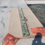
Received the boards, 3/4" (19mm) 4'x8' (1.2m x 2.4m) MDF,
So yup, it's officialy started, I have finalized the drawings and will post a detailed sketch later, one thing I realized tho is that each cabinet will weight around 100-120lb (about 60kg) without the drivers , So i m going to add some kind of dolly or add two casters to the back side of each cabinet so I can just tilt it toward the back and move it around if I need to.
I will start working on this but I have my schedule full until after October, so don't expect a lot of progress till then
hello everyone.
Received the boards, 3/4" (19mm) 4'x8' (1.2m x 2.4m) MDF,
So yup, it's officialy started, I have finalized the drawings and will post a detailed sketch later, one thing I realized tho is that each cabinet will weight around 100-120lb (about 60kg) without the drivers
, So i m going to add some kind of dolly or add two casters to the back side of each cabinet so I can just tilt it toward the back and move it around if I need to.I will start working on this but I have my schedule full until after October, so don't expect a lot of progress till then
Attachments
Could you clamp or otherwise affix a straight edged piece of timber and run the circular saw along that. Possibly you could mark out the actual wanted pieces and then cut areas not needed and tidy up the more manageable pieces on your table saw? A couple of ideas that may be of use or not
Some updates
Sorry for my long absents, I m getting married in a few weeks and barely have time for anything else.
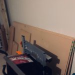
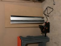
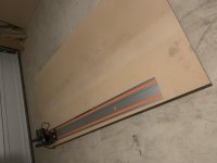
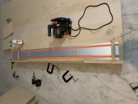
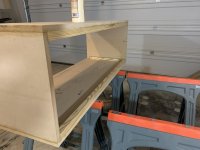
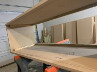
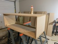
I had a little progress tho, I got a track saw but it feels cheap and flimsy, so to make it more accurate and avoide more cutting than necessary I made a little jig around it.
I just went with it without any planning but it turned out good, I secured the tracks tightly on a large board, glued some blacks around it to stop it from moving around and loosing its accuracy, for the next step I m gonna cut the board off with the saw on the track, this way the cut would be my guid to make the future cuts and it will be accurate (the same idea from a table saw sled jig but here the jig is stationary and the saw will move across). lesson learned tho, next time I wouldn't buy a track saw, a nice jig with a cheap circular saw would do the job just as good.
I don't think I will have much progress for the next month or so, so please be patient.
Sorry for my long absents, I m getting married in a few weeks and barely have time for anything else.
I had a little progress tho, I got a track saw but it feels cheap and flimsy, so to make it more accurate and avoide more cutting than necessary I made a little jig around it.
I just went with it without any planning but it turned out good, I secured the tracks tightly on a large board, glued some blacks around it to stop it from moving around and loosing its accuracy, for the next step I m gonna cut the board off with the saw on the track, this way the cut would be my guid to make the future cuts and it will be accurate (the same idea from a table saw sled jig but here the jig is stationary and the saw will move across). lesson learned tho, next time I wouldn't buy a track saw, a nice jig with a cheap circular saw would do the job just as good.
I don't think I will have much progress for the next month or so, so please be patient.
Attachments
Sorry for late replay
I wanted to have a permenant solution for future projects and I found a good deal on the track saw so I just went for it, hopefully this jig will serve me for a while, and I can cut long crosscuts by my self, next is to make the jig vertical kinda like what they have at home depot, shouldn't be that hard and there are a bunch of youtube videos about it.
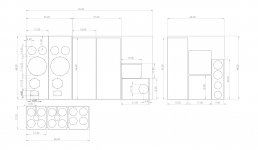
also I m working on the drawings as well, attached is the latest one.
yes that would be one solution but I wanted to avoid more cuts just to clean up the first cut and wasting more material than I should, if this jig turn out good and accurate enough, it may help others as well to build one
you know it has to be nice
I figured the cabinet would stay the same size, maybe some minor changes, and I will make the front baffle exchangable so if it turn out good, I can use the same cabinet and only build one more.
Can you "phone a friend" to assure safe cuts of these large MDF sheets?
If you can post the final drawings you may get support from another builder with a larger wood shop and more experience to discuss safe working methods.
I wanted to have a permenant solution for future projects and I found a good deal on the track saw so I just went for it, hopefully this jig will serve me for a while, and I can cut long crosscuts by my self, next is to make the jig vertical kinda like what they have at home depot, shouldn't be that hard and there are a bunch of youtube videos about it.
also I m working on the drawings as well, attached is the latest one.
Could you clamp or otherwise affix a straight edged piece of timber and run the circular saw along that. Possibly you could mark out the actual wanted pieces and then cut areas not needed and tidy up the more manageable pieces on your table saw? A couple of ideas that may be of use or not
yes that would be one solution but I wanted to avoid more cuts just to clean up the first cut and wasting more material than I should, if this jig turn out good and accurate enough, it may help others as well to build one
Or use a jigsaw? This is just a prototype, and it does not have to look nice.
you know it has to be nice
I figured the cabinet would stay the same size, maybe some minor changes, and I will make the front baffle exchangable so if it turn out good, I can use the same cabinet and only build one more.
Attachments
Last edited:
Progress !
Hi and happy new year!
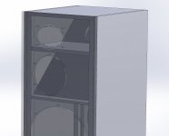
I finally made some progress with the cabinet and came across an issue (will upload some pics later),
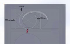
the STH horn cut out is about 100mm by 167mm but the Faital CD diameter is about 121mm, so I have to make the hole bigger for the CD to pass through and this will cause a few problems, the STH Horn dimension is 180mm by 120mm, so the hole would be a little larger than the horn itself, since it is not a big gap I guess I can use gasket or something to seal it, this is not my ideal solution but the only practical one I can come up with.
Also, since I have to cut a larger hole we have to move the whole horn assembly a little higher, about 10mm closer to the top and away from the midrange driver, I m not sure how this would affect the measurements.
I tried to come up with other solutions like make the rear panel removable and install the CD from the back but the mounting holes are in front of the CD and not possible to access through resonance chamber cutout. I also thought of making the front panel removable but with wieght of 1.5" mdf + heavy 15" woofer I dont think it is gonna be a good solution and I do not trust it not to resonate.
Please let me know what do you think and if you have any other suggestion/solution to this issue.
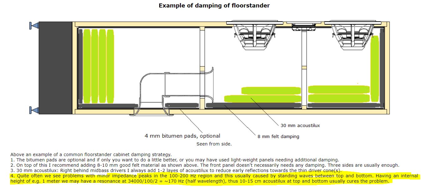
In another subject, I was reading about cabinet damping and I came across this from Troel Website:
so what do you guys think ? do you think it is possible to trust this methode and skip the camber or is it a better idea to go forward with the chamber, I just feel like it makes the build a little more complex ?
Hi and happy new year!
I finally made some progress with the cabinet and came across an issue (will upload some pics later),
the STH horn cut out is about 100mm by 167mm but the Faital CD diameter is about 121mm, so I have to make the hole bigger for the CD to pass through and this will cause a few problems, the STH Horn dimension is 180mm by 120mm, so the hole would be a little larger than the horn itself, since it is not a big gap I guess I can use gasket or something to seal it, this is not my ideal solution but the only practical one I can come up with.
Also, since I have to cut a larger hole we have to move the whole horn assembly a little higher, about 10mm closer to the top and away from the midrange driver, I m not sure how this would affect the measurements.
I tried to come up with other solutions like make the rear panel removable and install the CD from the back but the mounting holes are in front of the CD and not possible to access through resonance chamber cutout. I also thought of making the front panel removable but with wieght of 1.5" mdf + heavy 15" woofer I dont think it is gonna be a good solution and I do not trust it not to resonate.
Please let me know what do you think and if you have any other suggestion/solution to this issue.
In another subject, I was reading about cabinet damping and I came across this from Troel Website:
so what do you guys think ? do you think it is possible to trust this methode and skip the camber or is it a better idea to go forward with the chamber, I just feel like it makes the build a little more complex ?
Attachments

Last edited:
HAPPY NEW YEAR!
Could you make it such that part of the front panel (where the tweeter is) is removable? Then you could mount the horn+CD to the removable part of the front panel and then put the whole thing into the speaker.
I don't expect this to make a noticable difference. The wavelength of a 20 kHz sound is 17 mm, so 10 mm seems irrelevant.
The tuned box will be more efficient to absorb the standing wave. To get the same absorption without the internal box you'll have to stuff the entire box with quite a lot of absorbing material, and most materials are not very efficient to absorb low-frequency sound. However, if you want to go the Troels way, I'd recommend melamine foam absorbers -- this may work okay without too much stuffing, which is important to allow the bass reflex system to work well.
the STH horn cut out is about 100mm by 167mm but the Faital CD diameter is about 121mm, so I have to make the hole bigger for the CD to pass through and this will cause a few problems, the STH Horn dimension is 180mm by 120mm, so the hole would be a little larger than the horn itself, since it is not a big gap I guess I can use gasket or something to seal it, this is not my ideal solution but the only practical one I can come up with.
Could you make it such that part of the front panel (where the tweeter is) is removable? Then you could mount the horn+CD to the removable part of the front panel and then put the whole thing into the speaker.
Also, since I have to cut a larger hole we have to move the whole horn assembly a little higher, about 10mm closer to the top and away from the midrange driver, I m not sure how this would affect the measurements.
I don't expect this to make a noticable difference. The wavelength of a 20 kHz sound is 17 mm, so 10 mm seems irrelevant.
In another subject, I was reading about cabinet damping and I came across this from Troel Website:
so what do you guys think ? do you think it is possible to trust this methode and skip the camber or is it a better idea to go forward with the chamber, I just feel like it makes the build a little more complex ?
The tuned box will be more efficient to absorb the standing wave. To get the same absorption without the internal box you'll have to stuff the entire box with quite a lot of absorbing material, and most materials are not very efficient to absorb low-frequency sound. However, if you want to go the Troels way, I'd recommend melamine foam absorbers -- this may work okay without too much stuffing, which is important to allow the bass reflex system to work well.
Could you make it such that part of the front panel (where the tweeter is) is removable? Then you could mount the horn+CD to the removable part of the front panel and then put the whole thing into the speaker.
Hi mbrennwa!
That is true, I can do that, although it would make the veneering (or laminating) more difficult, also not a big fan of having the screws showing on the top part and not on the rest of the baffle.
maybe we cut a larger groove around the horn like 140x200 (instead of 120x180mm - 10mm recessed around the horn edges) and attach a same size 140x200 board to the back of the horn so the whole assembly can sit in a larger cut out and it won't look that bad, I m not sure if I explained it well, will attach drawings later.
The tuned box will be more efficient to absorb the standing wave. To get the same absorption without the internal box you'll have to stuff the entire box with quite a lot of absorbing material, and most materials are not very efficient to absorb low-frequency sound. However, if you want to go the Troels way, I'd recommend melamine foam absorbers -- this may work okay without too much stuffing, which is important to allow the bass reflex system to work well.
Nice! will do the resonance chamber then

That is true, I can do that, although it would make the veneering (or laminating) more difficult, also not a big fan of having the screws showing on the top part and not on the rest of the baffle.
maybe we cut a larger groove around the horn like 140x200 (instead of 120x180mm - 10mm recessed around the horn edges) and attach a same size 140x200 board to the back of the horn so the whole assembly can sit in a larger cut out and it won't look that bad...
A bit like an adapter ring? Sounds good to me.
Could you rear-mount the horn (like the ATC SM75-150 or Volt VM752 midrange) and do everything via a removable back?
Or would it be possible to mount the CD to the horn via the hole(s) of the wooer or midrange driver?
Yes like an adapter.
no I can't rear mount it, the screw holes to attach the CD to the horn is on the front face of CD and has no access from the back.
removable back and access from mid or woofer is also not possible since the CD/Horn will sit in the resonance chamber and can't access it from there, also mid section is sealed and from the woofer cutout even if I could reach all the way to the top of the cabinet where HF driver is, the bracings is on the way, I think our only option is either a removable top section as you described or an adapter plate.
Last edited:
What compression driver was it? I managed to install bulky hf10ak through sth100 hole, tight fit though. File/route from the backside of the frontpanel so that the frontpanel becomes rather thin from top (or bottom) of the sth100 mounting hole. Put one edge of the driver (+horn assembly) in first at an angle and then the rest with a rotating motion. Hard to describe, just think very thin frontpanel hope it helps, to avoid extra work. But then, it would be easier to tune the resonator through a bigfer opening like the adapter plate.
hope it helps, to avoid extra work. But then, it would be easier to tune the resonator through a bigfer opening like the adapter plate.What compression driver was it? I managed to install bulky hf10ak through sth100 hole, tight fit though. File/route from the backside of the frontpanel so that the frontpanel becomes rather thin from top (or bottom) of the sth100 mounting hole. Put one edge of the driver (+horn assembly) in first at an angle and then the rest with a rotating motion. Hard to describe, just think very thin frontpanel
Hi
HF10AK is 102mm in diameter but the driver here is HF107 which is 121mm, STH100 cutout is about 100mm

the drawings are attached.
Attachments
Last edited:
Hi
HF10AK is 102mm in diameter but the driver here is HF107 which is 121mm, STH100 cutout is about 100mm
the drawings are attached.
Ah, now I see, the drawing explains a lot. If I get this right, it's just 1mm missing... will it be possible to insert the CD+horn if you make the hole a bit elliptical (wider than 120mm, but only about 116mm tall or so) and then feed the CD through that hole at an angle, like tmuikku suggested?
No it is not 1mm, the cutout is about 100mm (not 120mm), and the CD diamater is 121mm, even if I make a bigger 116mm by 120mm elliptical hole, I still think it wouldn't be enough to fit the CD+Horn assembly through because of the thickness of materiel (about 38mm) unless I remove some material from the back, I will try it on a scrap piece.
Resurrection
Hi! And hope everybody is safe and healthy, it’s been a while and I have good news and bad news!
The bad news is that sadly I will not continue this project with TD15X anymore, it is not happening... well at least for me. I will explain more later.
The good news is that I’m not totally abandoning the project, I’m making some changes and adapting this project to my own situation and limitations, with new drivers!
As you know I was already building the prototype, So what happened ?!
Long story short, the size and weight of the cabinets was a deal breaker for me, each cabinet would be around 125lb - 140lb (~56Kg) without the drivers and felt and stuffing and hardware. This is not easy to work with if you don’t have help and this is absolutely not something you can build on a kitchen table or island, this will break your table, and you probably will hurt your back trying to move this beast, again this is my problem and not the design and all this could be easily avoided if I had more experience and with someone to help move things around.
But this project came to a halt when my wife saw the enormous size of the cabinet and how bulky it is for the first time, and asked if I really plan to put this in the living room!.. She was still supportive but you know, that is it...
This project was fun for me and I learned a lot and I hope everyone following this would understand my reasons, I apologize that sadly I can’t continue this as promised, my life changed since when we first started this project and for now this is not possible for me to continue the way we planned, I appreciate everybody who supported this project and helped along the way.
- Status
- This old topic is closed. If you want to reopen this topic, contact a moderator using the "Report Post" button.
- Home
- Loudspeakers
- Multi-Way
- Open Source "Tower XL"