IMO, this looks a very good concept, good size and shape for the midrange part, and some extra volume for the woofer. Some tests can be done using a IHA. If not successful, it isn't lost space.some updates on the design.
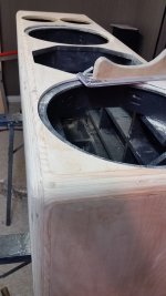
I added the IHA as suggested, the mid chamber is about 13 liters and the IHA is about 23 with the 18cm cutout on the back wall of the IHA and HF Driver+Horn will fit nicely there as well.
Maybe adding an extra vertical bracing in the woofer part, behind the driver? That should make the cabinet extra solid.
I am looking forward to test results of this incarnation. There is a refined and simple elegance achieved here which I hope delivers from theory to good test facts. This will be a great build.
1.) I'm out of my element here and trying to learn...I do grasp bass reflex port resonance and helmholtz resonance. Does unequal horizontal and/or vertical offset the the lower front ports have any effect on internal standing waves? How about unequal port diameters and lengths?
2.) Any suggestions about quality enclosure simulation software so I can learn more? Are the items OmniMic V2 and DATS acceptable for testing?...or too easily outgrown? These questions come to mind because I have many pairs of various aged mid-quality speakers and I want to restore/rebuild within reason so as to sell and fund my audio habit.
Thanks
IHA might work fine but prototype box is mandatory I think. Post #858 drawing, simple construction, good! but the IHA port is in a place that it is difficult to tune unless removable front panel or some clever adjustable vent one can adjust through the horn hole by hand.
The IHA port might be most effective at the very top, it is all pressure nodes of standing waves there!")
But, it might be just as effective (regarding mids leaking through the "main" ports) to just put damping material for the whole top section (above woofer) and not worry too much about the IHA port.
It is interesting to see how it turns out
The IHA port might be most effective at the very top, it is all pressure nodes of standing waves there!
But, it might be just as effective (regarding mids leaking through the "main" ports) to just put damping material for the whole top section (above woofer) and not worry too much about the IHA port.
It is interesting to see how it turns out
But, it might be just as effective (regarding mids leaking through the "main" ports) to just put damping material for the whole top section (above woofer) and not worry too much about the IHA port.
I think so too, a thick section of melamine foam up top instead of the IHA, will effectively kill most resonances there, add a half as thick layer at the bottom of the enclosure, and it should be a very "dead" box indeed.
I was convinced into ordering some melamine foam off ebay, in account of it's very dense OCF structure it is far superior to any polyurethane foam I've tried.
It will be my "go to" damping material for the foreseeable future, perhaps spiced up with wool felt in some cases.
I've had very good results with melamine foam in the Monkey Coffin. However, the melamine will not magically absorb the 145 Hz mode of the current Tower XL design. Sheep wool works better to absorb low frequency sound, but is also limited.
The idea of the IHA is that it presents a sink for sound waves at the frequency of the IHA tuning, instead of reflecting it back into the bass chamber. This is different to a hard wall reflector covered by damping material in an attempt to absorb the sound.
The idea of the IHA is that it presents a sink for sound waves at the frequency of the IHA tuning, instead of reflecting it back into the bass chamber. This is different to a hard wall reflector covered by damping material in an attempt to absorb the sound.
Different materials do have different uses.
Did not realize you had any modes triggering at 145hz in this, but not surprised, have not tried running any sims.
145hz might be a bit hard to deal with, regardless of which solution you implement. You might have some problems at around 300hz as well, but that's easier.
It would be easy to push the numbers of enclosure dimensions in a different direction to trigger more easy to deal with modes, but it seems that choices have been made and decisions set, and I will not try to convince change from a decision done "by heart".
In post #858 the woofer is roughly midway of the frontpanel height, so the lowest standing wave might be non existent, according to hornresp and my prototype.
Prototype is needed to see what the lowest leaking standing wave mode actually is and then tune the IHA to that. The section at the top will make the enclosure longer and lower the standing waves in frequency, also the woofer is not at the center of the box "height" anymore due to this elongated path.
Prototype is needed to see what the lowest leaking standing wave mode actually is and then tune the IHA to that. The section at the top will make the enclosure longer and lower the standing waves in frequency, also the woofer is not at the center of the box "height" anymore due to this elongated path.
Last edited:
... Did you include the alternate tapering top?
Would you mind sharing the numbers on that hornresp sim? Just a picture of the input window please. Not being lazy, but I just sneak in a couple minutes of diyaudio every now and then, packing and prepping for vacation, so very limited time for audio stuff.
Would you mind sharing the numbers on that hornresp sim? Just a picture of the input window please. Not being lazy, but I just sneak in a couple minutes of diyaudio every now and then, packing and prepping for vacation, so very limited time for audio stuff.
Last edited:
... Did you include the alternate tapering top?
Would you mind sharing the numbers on that hornresp sim? Just a picture of the input window please. Not being lazy, but I just sneak in a couple minutes of diyaudio every now and then, packing and prepping for vacation, so very limited time for audio stuff.
Hi, nope didn't include the tapering top, but one could try it in hornresp.
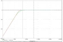
It is just a concept that seems to hold true with my prototype box. Use Hornresp MLTL wizard, tune parameters for your box, adjust L12 con (driver position) and see the lowest resonance come and go. Driver at ~halfway the resonance goes away, seems to be at the half wavelength on the longest dimension (attached, ~106cm height, ~160Hz lowest standing wave).
One could tame the lowest resonance with the IHA, and target some of the other resonances with the driver / port position. Thus, prototype necessary to see what the midrange leakage from the reflex port is, and then try to address them as much as needed, if needed.
ps.
All this is just one experiment of rather inexperienced tinkerer, so my advice might be just in the ballpark, which doesn't tell much for optimal performance. Optimal performance must be done with prototype box
Attachments
Last edited:
It is just a concept that seems to hold true with my prototype box. Use Hornresp MLTL wizard, tune parameters for your box, adjust L12 con (driver position) and see the lowest resonance come and go. Driver at ~halfway the resonance goes away, seems to be at the half wavelength on the longest dimension (attached, ~106cm height, ~160Hz lowest standing wave).
This is as good as you can expect with these dimensions, really, since the driver is ~midway, and the resonance port of the enclosure will be lifted a bit up from the bottom, the only wiggles you have to care about would be the stuff over 300hz.
It is the distance driver-to-port both directly and via reflecting surfaces that is most important.
If the driver is closer to the bottom in this sim, it will be much worse. Top-to-bottom reflections are important, but not quite as important as driver-to-surfaces-and-port. IMO + some variations pending on other design decisions and tons of salt etc.
Around 108cm would be about 280hz or so, distance drives-top-bottom where the port is. But the port is a bit up from the bottom, and the top will have a tilt that effectively breaks the path between parallel surfaces. So a bit of damping material and some other careful considerations should make it good to 4-500hz or so methinks.
So if this is in the right kind of ballpark, IHA = waste of time.
Edit:
LineSource, Love those edges, gets out the beautiful layers soooo nicely, just a touch of lintseed oil and it's done.
Last edited:
...the only wiggles you have to care about would be the stuff over 300hz.
Really? I am not sure but I believe the x-over point would be close to or lower than 300 Hz, so these resonances would not be excited anyway. Also, damping a > 300 Hz resonance with a bit of wool or melamine works better than at the lower frequencies.
I found a baffle edge treatment picture of a 1" quarter round on a 12" midrange MTM plywood cabinet.
Note the hand sanding block.
Note no blood stains.
? Any early builder using DSP with tri-amps?
1.25 radius, 15" MTM cabinet. Hand sanding was used after router, several passes were used.
Large plywood square base screwed to stock router base.
Really? I am not sure but I believe the x-over point would be close to or lower than 300 Hz, so these resonances would not be excited anyway. Also, damping a > 300 Hz resonance with a bit of wool or melamine works better than at the lower frequencies.
Exactly.
/On a mobile in Bali far awsy from my computer.
Sorry for long absent, got busy with real world stuff.
So it looks like we have a very solid starting point. Hoping to start cutting very soon, in next few weeks, I ll be on and off again, since this is a busy month but will not abandon this project.
any other ideas or consideration before prototyping ?
So it looks like we have a very solid starting point. Hoping to start cutting very soon, in next few weeks, I ll be on and off again, since this is a busy month but will not abandon this project.
any other ideas or consideration before prototyping ?
To give the project a startup again, I did some study on the smaller Tower XL, the last proposal done by Aatto.
Cabinet:
For the dimensions I used Aatto's drawing of post #858. I did adapt my own drawings also to calculate new volumes and driver positions, see in attachement.
The netto volume for the woofer now is about 180 litres and for the midrange 13 litres.
Woofer basreflex system:
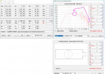
I used the TSP of the AE TD15X-8 as measured by Aatto a time ago, see Leap driver model in attach. To avoid SPL boost around 100 Hz, fB has to be chosen at 22 Hz or lower.
The port is realized with two tubes of 10 cm diameter each and 40 cm long. Calculating the minimum required port area Sv for this 15 inch driver with Sd = 855 cm2 and xmax = 14 mm conform R. Small (Sv larger than 0.8 x fB x Vd), Sv has to be larger than 211 cm2. That are 2 tubes of 12 cm diameter each. I have chosen 10 cm tubes to reduce the tube length to 40 cm, that means a port area sufficient up to 10 mm excursion peak.
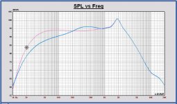
This is the result of the system simulation:
AE TD 15X-8 in VB = 180 L, fB = 22 Hz, F3 = 33.8 Hz, F6 = 25.9 Hz, F10 = 20.2 Hz.
This is a basreflex system more damped than a B4 alignment at the same system frequency. See the comparison of the low frequency SPL (green) versus a B4 (red) in the plot. In attach also the SPL of the woofer system on infinite baffle (pink) and in full space (blue).
The speaker that can be designed will have a sensitivity of 88 dB @ 2.83 Vrms, 1m and -3 dB at 34 Hz, full space.
So far the first input for the design from my side.
Cabinet:
For the dimensions I used Aatto's drawing of post #858. I did adapt my own drawings also to calculate new volumes and driver positions, see in attachement.
The netto volume for the woofer now is about 180 litres and for the midrange 13 litres.
Woofer basreflex system:
I used the TSP of the AE TD15X-8 as measured by Aatto a time ago, see Leap driver model in attach. To avoid SPL boost around 100 Hz, fB has to be chosen at 22 Hz or lower.
The port is realized with two tubes of 10 cm diameter each and 40 cm long. Calculating the minimum required port area Sv for this 15 inch driver with Sd = 855 cm2 and xmax = 14 mm conform R. Small (Sv larger than 0.8 x fB x Vd), Sv has to be larger than 211 cm2. That are 2 tubes of 12 cm diameter each. I have chosen 10 cm tubes to reduce the tube length to 40 cm, that means a port area sufficient up to 10 mm excursion peak.
This is the result of the system simulation:
AE TD 15X-8 in VB = 180 L, fB = 22 Hz, F3 = 33.8 Hz, F6 = 25.9 Hz, F10 = 20.2 Hz.
This is a basreflex system more damped than a B4 alignment at the same system frequency. See the comparison of the low frequency SPL (green) versus a B4 (red) in the plot. In attach also the SPL of the woofer system on infinite baffle (pink) and in full space (blue).
The speaker that can be designed will have a sensitivity of 88 dB @ 2.83 Vrms, 1m and -3 dB at 34 Hz, full space.
So far the first input for the design from my side.
Attachments
-
20190803 Tower XL cabinet drawing.pdf43.3 KB · Views: 51
-
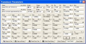 20190804 Tower XL AE TD15X-8 Aatto Leap driver model.JPG102.3 KB · Views: 371
 -
 20190804 Tower XL AE TD15X-8 Aatto SPL versus B4.JPG54.1 KB · Views: 358
 -
 20190804 Tower XL AE TD15X-8 Aatto SPL infinite baffle and free space.JPG142.1 KB · Views: 358
Last edited:
Hi Matthias,
Thanks for feedback, I didn't look yet to the port resonance.
We can chose fB a little higher for a more short port, but I don't prefer because some SPL boost will appear around 100 Hz. Or making the tube diameter lower, but in that case there will be more port noise.
With the 8 inch midrange the X-over frequency can be lower than 300 Hz... And probably also steep filtering will be applied.
Edit:
Simulating in Leap with 2 x 10 cm tubes of 40 cm long, fB = 22 Hz, the port resonance is 375 Hz.
With 2 x 10 cm tubes of 25 cm long, fB = 26.5 Hz, the port resonance is 570 Hz.
With fB = 26.5 Hz for this woofer in 180 L volume, the SPL boost becomes 0.12 dB around 100 Hz. That is acceptable.
So I think it is better to decrease the port length to 25 cm and use 2 x 10 cm tubes.
Last edited:
Hi pal and thanks for well detailed work.
88db is a little shy of the 90db goal but compromises... but i m happy with the low frequencies respond, looking good.
sorry for my late replies, I m very busy with real world stuff, but still getting ready to start cutting, I bought a table saw and a router, should be good enough to start building, I still need a good table saw blade and some router bits to start working hopefully very soon.
Stay Tuned..
88db is a little shy of the 90db goal but compromises... but i m happy with the low frequencies respond, looking good.
sorry for my late replies, I m very busy with real world stuff, but still getting ready to start cutting, I bought a table saw and a router, should be good enough to start building, I still need a good table saw blade and some router bits to start working
hopefully very soon.Stay Tuned..
- Status
- This old topic is closed. If you want to reopen this topic, contact a moderator using the "Report Post" button.
- Home
- Loudspeakers
- Multi-Way
- Open Source "Tower XL"