Yes they are, because he can get the Faital Pro 15FH520 for 178£ each from Bluearan, and the shipping would be maybe 3£ each, no more costs or taxes. So about 181£ total per driver.
I guess that means you are comparing the Faital price with VAT/taxes included to the AE price before adding VAT/taxes. Also, international shipping from Blue Aran is certainly more (it was with my recent order for the Monkey Coffin). We need to make sure we don't compare apples with oranges (VAT included or not, international vs local shipping). But I agree that the AE drivers are not cheap.
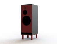
I have done a simulation with the AE TD15X-8 in a Tower XL cabinet with 150 L available for the woofer excl. port. That means a cabinet with dimensions of W x H x D = 46 x 110 x 50cm.
A port of 44 cm total length and 195 cm2 port area.
That looks very good! With a driver with such parameters, we can make one proposal for all, no options for the port anymore (I think so).
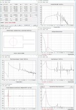
AE TD 15X-8 in VB = 150 L and FB = 24.6 Hz, F3 = 35.3 Hz, F6 = 27.7 Hz, F10 = 22.5 Hz
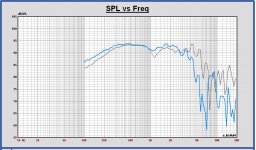
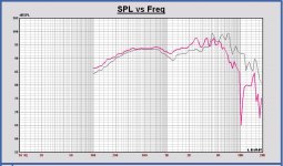
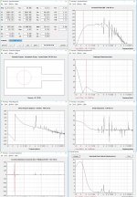
See also the SPL and groupdelay plot, AE TD15-8 in blue and Faital Pro 15FH520 in green to compare.
SPL Plot

Groupdelay plot

I propose to find another driver as second woofer, one with comparable TSP of the AE TD15X-8.
Kaffimann:
Can you check this also please? We have to be sure that I haven't made a mistake here.
A port of 44 cm total length and 195 cm2 port area.
That looks very good! With a driver with such parameters, we can make one proposal for all, no options for the port anymore (I think so).
AE TD 15X-8 in VB = 150 L and FB = 24.6 Hz, F3 = 35.3 Hz, F6 = 27.7 Hz, F10 = 22.5 Hz
See also the SPL and groupdelay plot, AE TD15-8 in blue and Faital Pro 15FH520 in green to compare.
SPL Plot
Groupdelay plot
I propose to find another driver as second woofer, one with comparable TSP of the AE TD15X-8.
Kaffimann:
Can you check this also please? We have to be sure that I haven't made a mistake here.
Some thoughts:
1: Why 22mm mdf? Most of the world will have more difficulty getting it, it's more expensive and offers no performance advantage over 18mm when properly braced.
2: Put if on short legs and exit the round ports on the bottom. This allows tubes to be used and flares are more available commercially and it allows the port to actually be tuned easily to the enclosure by testing, and adding length/ cutting the tubes to fit. Press fit and blutak hold well enough for testing.
Additional advantages; allows damping to be placed more effectively inside the enclosure without blocking the path between driver rear and port entrance. Also means any midrange spill from the port is not directly entering the listening space. Even better if the room is carpeted.
It's easier to draw on my laptop so will add a clarifying sketch later.
3: Irrespective of what the T/S and sims show, give the mid a larger enclosure, maybe a simple tube to the rear baffle with increasing density of damping to the end.
4: Why a dome for the HF? Plenty of good AMTs and ribbons out there.
5: Where's the bracing?
6: Golden ratios are vastly overrated in terms of enclosure dimensions actually affecting performance.
Last edited:
I guess, the mdf (or plywood) thickness is for the sketch the important part is the internal dimension, here in US we have 3/4" which is 19mm and 1" which is 25.4mm, no 22mm or 18mm here  but that is just small details.
and if I remember correctly Paul said he accounted for port vol and also bracing ... but not drawn in the rough sketch.
one questions tho, regarding the AMTs, I never heard an AMT so no comments there but but don't AMTs usually have very high Fs ? and also pricey.
I prefer domes over ribbons, just based on what i usually listen to, for more relaxed (jazz or vocal centered) musics I do like ribbons.
but that is just small details.and if I remember correctly Paul said he accounted for port vol and also bracing ... but not drawn in the rough sketch.
one questions tho, regarding the AMTs, I never heard an AMT so no comments there but but don't AMTs usually have very high Fs ? and also pricey
.I prefer domes over ribbons, just based on what i usually listen to, for more relaxed (jazz or vocal centered) musics I do like ribbons.
Most of the reasonably priced AMTs I looked at (everything in madisound and parts express availability) had something that didn't meet our requirements, ie sensitivity, fs, impedance, etc. Some of the Fountek ribbons looked good, and there are a few domes (edit: or ring radiators) that would work well. Limiting to 8 ohm nominal impedance limits our options quite a lot. Allowing a 6 ohm would jncrease options, and we might be able to increase the impedance in crossover design, especially if its a higher sensitivity model.
cool, that is great Paul
I ll go ahead and order the drivers then, TD15X or TD15H ? and TD8M for mids for AE version, correct ?
Hi Aatto,
The AE TD15X is the best choice IMO. It has the highest sensitivity.
The AE TD15H goes lower but has less sensitivity.
It is easy to understand, the 15H has more Mms than the 15X and both drivers have the same compliance. So, they have the same absolute SPL at low frequencies, but not for higher frequencies, then the 15X goes louder. Looking relative the 15H goes deeper.
You have to choose what you prefer, lowest F3 or highest sensitivity.
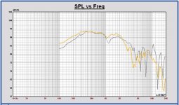
AE TD 15X-8 in VB = 150 L and FB = 24.2 Hz , F3 = 35.3 Hz, F6 = 27.7 Hz, F10 = 22.5 Hz – 96.1 dB half space
AE TD 15H-8 in VB = 150 L and FB = 24.2 Hz, F3 = 31.3 Hz, F6 = 25.5 Hz, F10 = 21.4 Hz – 94.6 dB half space
SPL AE TD15X (blue) and AE TD15H (yellow)

GD AE TD15X (blue) and AE TD15H (yellow)

For the TD8M vs. the TD6M, let me do first a DI investigation in Leap based on the off axis measurements of AE. I am a little afraid the DI of the TD8M becomes too high around 1500 Hz and maybe I can see something in simulation. Now we only know from John that it sounds well. I have the results soon.
Brett,
Also some comments from my side on your remarks:
- the midrange enclosure can be about 15 L netto in this cabinet, the driver has a Vas of 13 L. I think that is enough, and a closed box filled with sheep wool if I may choose it.
- a rectangular port seems to have some advantages, Kaffimann can tell you.
It is more solid also than a round PVC tube.
- I will not discuss the golden ratio, but asymmetric driver positions show large improvements in more uniform off axis responses and smoother DI. I haven't implemented it that way in earlier projects, but now simulations show a lot of improvement. Also ATC does it in their speakers.
Hi Aatto,
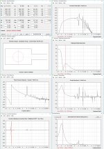
It looks good for the AE TD8M compared with the AE TD6M.
The SPL curves on and off axis are more linear and smooth for the TD8M.
The calculated DI of both drivers is almost equal up to 2.5 kHz. Above 2.5 kHz, the DI of the TD8M is a little higher.
That both DI curves are almost equal, proves that the TD8M has some smooth cone breakup.
Remark this is a calculated DI in a single horizontal plane of only +/- 52.5 degrees. But it gives a good indication already.
Based on these results, best choice is the TD8M!
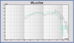
Some plots in attach. SPL at 0, 15, 30 and 45 degrees and the calculated DI, both drivers compared. The TD8M curves in color in all plots.
It looks good for the AE TD8M compared with the AE TD6M.
The SPL curves on and off axis are more linear and smooth for the TD8M.
The calculated DI of both drivers is almost equal up to 2.5 kHz. Above 2.5 kHz, the DI of the TD8M is a little higher.
That both DI curves are almost equal, proves that the TD8M has some smooth cone breakup.
Remark this is a calculated DI in a single horizontal plane of only +/- 52.5 degrees. But it gives a good indication already.
Based on these results, best choice is the TD8M!
Some plots in attach. SPL at 0, 15, 30 and 45 degrees and the calculated DI, both drivers compared. The TD8M curves in color in all plots.
Attachments
Most of the reasonably priced AMTs I looked at (everything in madisound and parts express availability) had something that didn't meet our requirements, ie sensitivity, fs, impedance, etc. Some of the Fountek ribbons looked good, and there are a few domes (edit: or ring radiators) that would work well. Limiting to 8 ohm nominal impedance limits our options quite a lot. Allowing a 6 ohm would jncrease options, and we might be able to increase the impedance in crossover design, especially if its a higher sensitivity model.
we still have some good 8ohm options, adding pads to tweeter can be avoided
My apologies for this. I initially viewed your sketches on a 10"tablet and took the mid driver representation as being a very small enclosure.- the midrange enclosure can be about 15 L netto in this cabinet, the driver has a Vas of 13 L. I think that is enough, and a closed box filled with sheep wool if I may choose it.
I'd love to hear them, especially with some measurements / evidence to back them up.- a rectangular port seems to have some advantages, Kaffimann can tell you.
However, apart from the increased difficulty of making roundovers and tuning precisely, the increased surface area to volume over a cylinder is likely to lead to increased turbulence.
And how is that relevant? It's not really under a lot of loading.It is more solid also than a round PVC tube.
If you are referring to increased rigidity of the enclosure by the slot port being in effect a brace, just add another brace. Bracing does not have to be the same thickness as the enclosure walls to be extremely effective.
Asymmetrical driver arrangement I have no problems with, but GM for enclosure internal volumes is meaningless in practice with well placed damping. There are more important considerations such as baffle step.- I will not discuss the golden ratio, but asymmetric driver positions show large improvements in more uniform off axis responses and smoother DI. I haven't implemented it that way in earlier projects, but now simulations show a lot of improvement. Also ATC does it in their speakers.
Sure, ATC do it, but I think they're just going for simplest cheapest. I do note though that the EL150, (I think) their most expensive domestic enclosure does not.
AST21560. The smaller one would also likely work well too.Most of the reasonably priced AMTs I looked at (everything in madisound and parts express availability)
As you're looking at ~$US750 for the LF and MR drivers per channel, claiming it is too expensive seems a tad odd.
Brett: I just want to adress some of your concerns, there may be others that share your thoughts. My calculations are included some minimal but adequate bracing, it is not specified, but it's there. I strongly advise against having the port under the enclosure, it has the potential of significantly inducing room loading (trying to avoid this as much as possible), and will cause phase issues. I personally agree that ca 18mm decent quality ply is a better choice than 22mm mdf. It is true that a rectangular port has a more dampening effect that a round port, but the difference in regards to turbulence is negligible, because a round port will provide turbulence everywhere around it, vs a rectangular port will have the turbulence mostly on the inside of the cabinet and on the same side and in the same place regardless of loading. The biggest difference is the drag resistance across surface area, which may be somewhat comparable to light stuffing in a tube. On the front of the enclosure the air speed of a rectangular port will be so low, long story short: it is a waste of time being concerned of turbulence. A round port however, may have turbulence on the exit, and needs some attention to detail in dealing with this.
Paul: How much space do you need to have for the mid and tweet compartment? Should I cut off 15 or 20 or xx cm on top for the calculation?
Edit: numbers sans material for my benefit (changing computers alot): 46 (41,5) * 110 (98,2) * 50 (44,7)
Paul: How much space do you need to have for the mid and tweet compartment? Should I cut off 15 or 20 or xx cm on top for the calculation?
Edit: numbers sans material for my benefit (changing computers alot): 46 (41,5) * 110 (98,2) * 50 (44,7)
Last edited:
Some thought:
Choosing the TD8M midrange, what will be the alternative 8 inch midrange choice? IMO, we have to try to make the same driver configuration for the two options if possible. Otherwise we will make two different speakers in some way.
Some AE driver dimensions can be found here, Index of /pdfs
Choosing the TD8M midrange, what will be the alternative 8 inch midrange choice? IMO, we have to try to make the same driver configuration for the two options if possible. Otherwise we will make two different speakers in some way.
Some AE driver dimensions can be found here, Index of /pdfs
Paul: How much space do you need to have for the mid and tweet compartment? Should I cut off 15 or 20 or xx cm on top for the calculation?
Edit: numbers sans material for my benefit (changing computers alot): 46 (41,5) * 110 (98,2) * 50 (44,7)
To obtain 150 L netto volume for the woofer, cut off is 17.3 cm.
46 (41,5) * 110 (80.9) * 50 (44.7) = 150 L
For the port I took 195 cm2 and the port length (3 + 39 + 2.2 + 2.5) cm = 46.7 cm. With this length FB = 24 Hz in Leap.
Once the midrange compartiment and the bracing are defined, the woofer internal enclosure shape will look some different probably, but with the same volume of 150 L. We can adapt the cabinet heigth a little to fix that.
Last edited:
To give you my personal opinion about this, I more prefer a symmetric position of the driver on the front baffle, to keep the same dispersion in the horizontal plane. But combined with some improvements for diffraction by a more curved front panel.Asymmetrical driver arrangement I have no problems with, but GM for enclosure internal volumes is meaningless in practice with well placed damping. There are more important considerations such as baffle step.
Sure, ATC do it, but I think they're just going for simplest cheapest. I do note though that the EL150, (I think) their most expensive domestic enclosure does not.
For this project there was a demand to keep the cabinet simple. I think a asymmetric position is the best solution then.
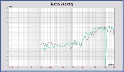
Here you go. The voltage is equal for all, just for comparison everything is the same except the drivers. Both the FH520 and the FH500 are slightly over their xmax at this voltage by ca 0.5mm, while the TD15X is well within it's comfort zone, but uses more travel than the other drivers.
If you want to force feed the design this much power (in pure sine sweep it is a problem, music should be fine with even more power than this), the Faital drivers should have a HP filter. The TD15x has lower group delay under 30hz, but also lower output because of parameters and loading/resistance in relation to box and port.
My personal choice would still be the 15FH500 because of the smooth predictable response, better response under 30hz than the 15FH520, and (in my case) much lower price than TD15X.
Attachments
Last edited:
Kaffimann,
Thanks, I will look later in detail, other jobs to do now.
But already this point. Also in my simulations I see that the Faitals have a group delay peak around 20 Hz, and the AE TD15X doesn't have. You also see in the SPL shape. A group delay peak means a more resonant tuning, I think we have to avoid it if possible. IMO the reason is the lower fs, larger Vas and maybe also the lower Qts of the AE. The Vas/Vb ratio is different for both applications. I will do that investigation where it comes from.
Edit: I think it is the fb/fs ratio which is higher for the AE system. In a way there is more damping of the driver at the fB frequency.
Last edited:
- Status
- This old topic is closed. If you want to reopen this topic, contact a moderator using the "Report Post" button.
- Home
- Loudspeakers
- Multi-Way
- Open Source "Tower XL"