Will mean most drivers change subjective character to the better using resonance plus inductance compensation networks to linearize drivers impedance and experience is that is also the case using a active XO system, so suggest for these trials with miniDSP to find the optimal XO topology that add those components so that sonic improvement is also present for the active trial setup and those components shall be used anyway down the road, also for the subjective worry about the port such a network can make a change.
I don't understand this (I am not a native English speaker). Could you please break this down to a few short(er) sentences?
So the assumption of Byrtt is that conjugate networks sonically improve filter loaded driver's performance.
@Byrtt : Can you back this up?
I have understood that Byrtt indicates that a digital version of a passive filter, needs to be an exact copy of the passive filter version, which means inclusive the compensation networks influence.
In our EL3 digital version, the targets were the voltage xo transfers of the passive version, it is a 1:1 copy of the passive xo, inclusive compensation networks... pfff
")
I had a look at three different filter versions using Vituix. The attachment shows the simulation results. At the beginning I tried hard to keep the driver response curves (acoustic) as close as possible to the theoretical target curves. However, I found that I can achieve better overall system response if I allowed some flexibility (cleaner summed response at the x-over frequencies, smoother off-axis response).
The three filter versions are as follows:
Before we go ahead with implementing these filters in the miniDSP, I'd like get some feedback on the simulation results. What do you like about those simulations, what is not to like? Is there anything obvious that needs to be improved?
The three filter versions are as follows:
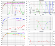
- The first six-pack shows the "20190114-EL3" version, which is a revised version of what I showed in post 607. I tweaked the part values to reduce the stop-band leakage (a lot -- note the different y-axis scale). I also achieved much smoother power response (blue curve).
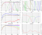
- The second six-pack shows the "20190116-EL4" version, which was derived from post 654, but tweaked some part values a bit to achieve good off-axis response and a bit better summed response at the x-over frequencies.
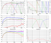
- The third six-pack shows the "20190116-Conventional3rd" version, which is a conventional x-over with 3rd order slopes (acoustical) that does not use the "notch elements" of the elliptic filters. I started from the Butterworth targets and tweaked it for good overall system response.
Before we go ahead with implementing these filters in the miniDSP, I'd like get some feedback on the simulation results. What do you like about those simulations, what is not to like? Is there anything obvious that needs to be improved?
Attachments
Last edited:
Byrtt,
For the EL3 biquad miniDSP version I made for Matthias, the voltage transfers of the passive xo are chosen as the filter targets. In that way it is inclusive the influence of the impedance compensation networks. It was the reason we did it that way to have an exact copy of the passive filter version in the miniDSP.
I don't understand this (I am not a native English speaker). Could you please break this down to a few short(er) sentences?
So the assumption of Byrtt is that conjugate networks sonically improve filter loaded driver's performance.
@Byrtt : Can you back this up?
I have understood that Byrtt indicates that a digital version of a passive filter, needs to be an exact copy of the passive filter version, which means inclusive the compensation networks influence.
In our EL3 digital version, the targets were the voltage xo transfers of the passive version, it is a 1:1 copy of the passive xo, inclusive compensation networks... pfff
Agree technically/objective miniDSP response is there now and those networks won't make any response difference for miniDSP setup as Paul points out, its all about the subjective difference that ears tell that can't be backed up on paper, although technically we can probably agree those networks damp some of the electric backwave from microphonic/loose spring oscilating behavour of transducer.
It doesn't look we agree much here : ) but also i don't know if you guys have experimented AB such networks into pure active system setup and if you haven't suggest try it out, for some woofers especially the resonance compensation network can be up to a brutal change to the better or close to night day experience, and those thirdteen components are not out of the window in they anyway is part of the final passive network.
Very interesting project, expecially 'cause it will be open source.
Anyway please seriously consider to adopt an appropriate and internationally recognized license such as Creative Commons' ones.
Due to the - reasonable - limitations imposed, I would suggest the Attribution-NonCommercial-ShareAlike 4.0 International (CC BY-NC-SA 4.0) license:
Creative Commons — Attribution-NonCommercial-ShareAlike 4.0 International — CC BY-NC-SA 4.0
Last but not least, here's a collection of resouce i've collected:
DIY - Open Digital Fidelity Audio Station
...
- The first six-pack shows the "20190114-EL3" version, which is a revised version of what I showed in post 607. I tweaked the part values to reduce the stop-band leakage (a lot -- note the different y-axis scale). I also achieved much smoother power response (blue curve).
- The second six-pack shows the "20190116-EL4" version, which was derived from post 654, but tweaked some part values a bit to achieve good off-axis response and a bit better summed response at the x-over frequencies.
- The third six-pack shows the "20190116-Conventional3rd" version, which is a conventional x-over with 3rd order slopes (acoustical) that does not use the "notch elements" of the elliptic filters. I started from the Butterworth targets and tweaked it for good overall system response.
I think the third option looks really sweet, the roll-off is nice and smooth, and the individual drivers seem to work well within their pass band.
The second option seems very nice too.
What is the difference in component count between #2 and #3, and will the cap values be higher for one filter than the other?
Thinking about cost and complexity here.
Gentlemen,
To make the design procedure even more complicated that it alreday is (poor Paul!):
Have you seen this thread? A little addition to multiway crossovers a la Linkwitz: multi-cascading
To make the design procedure even more complicated that it alreday is (poor Paul!):
Have you seen this thread? A little addition to multiway crossovers a la Linkwitz: multi-cascading
Agree technically/objective miniDSP response is there now and those networks won't make any response difference for miniDSP setup as Paul points out, its all about the subjective difference that ears tell that can't be backed up on paper, although technically we can probably agree those networks damp some of the electric backwave from microphonic/loose spring oscilating behavour of transducer.
The simple engineering answer is probably something like my post 612: If we use an amplifier with a high damping factor in the active/DSP setup (which I do), the driver impedances do not affect the voltage at the driver terminals (=voltage at the amplifier output). However, I am not saying that this is the end of the stroy. If you guys want me to already add the impedance compensation networks to the drivers, I can do that.
Very interesting project, expecially 'cause it will be open source.
Anyway please seriously consider to adopt an appropriate and internationally recognized license such as Creative Commons' ones.
Due to the - reasonable - limitations imposed, I would suggest the Attribution-NonCommercial-ShareAlike 4.0 International (CC BY-NC-SA 4.0) license:
Creative Commons — Attribution-NonCommercial-ShareAlike 4.0 International — CC BY-NC-SA 4.0
The question is if we need a license, and what it can do for us, and if it's not too late to put the licence in place. I honestly have no clue about these things.
The license you suggested seems to prohibit using the design commercially. Do we really want this? I'd actually be rather happy if someone would sell a Monkey Coffin kit (or even a finished speaker) -- as long as proper credit is given to what we're doing here.
I think the third option looks really sweet, the roll-off is nice and smooth, and the individual drivers seem to work well within their pass band.
The second option seems very nice too.
What is the difference in component count between #2 and #3, and will the cap values be higher for one filter than the other?
Thinking about cost and complexity here.
The number of parts in options (1) and (2) is the same as explained in post 654. The capacitors in the midrange filter are larger in the EL3 (33 uF and 82 uF) than in the EL4 (22 uF). Option (3) has 6 inductors, 5 capacitors, and 2 resistors (not including the impedance compensation parts, which are about the same for all designs). The series capacitor for the midrange is 33 uF.
I agree that we need to keep an eye on parts count and complexity, but let's say that the current EL3/EL4 complexity is just ok (but let's not get more complex).
I'd be interested in your thoughts about the electro-acoustics of the three filter designs. Is there anything to tweak or improve?
Have you seen this thread? A little addition to multiway crossovers a la Linkwitz: multi-cascading
I only read the first post of that thread (will read on when I have some time). I am not sure, but my gut feeling says that the extra cascading is an interesting idea in theory, but it does not do much in practical terms because the x-over frequencies are "far" apart from each other. Also, such a filter cascade will be huge and extremely complex to build.
...
I'd be interested in your thoughts about the electro-acoustics of the three filter designs. Is there anything to tweak or improve?
...
I do not mind sharing my opinion, as long as everyone understands that I am merely another amateur, making assumptions and doing my best to be difficult, and at the same time hoping to avoid starting a flame-war.
The Elliptic filters have a sharper initial roll off (*duh*), but they also exibit higher group delay which might be audible at these frequancies, the higher group delay at xo freq might also be the reason they sound more "lively" and "engaging". Elliptic filters are a bit of a double edged sword in this regard, and on some recordings the higher GD might sound awesome, on other recordings it might become annoying, but no compromise is without sacrifice.
The Butterworth filters are not perfect either, and have a more relaxed roll-off, I am a sucker for pretty curves, and those curves look pretty nice to me, also the group delay seems reasonably well controlled. The individual drivers seem to behave very nicely, complete response is not far off the EL4 solution.
Phase response seems relatively similar between the options, I know it's probably not very popular to enter another horse just minutes before the race is on, but I can not keep from wondering how it would look with 3rd or higher order Bessel filters mixed in. GD would perhaps be lower, and there might be something to be done with the phase response. It would require more adaption work to get 100%, but I am hoping it might be worth it.
If someone more experienced would come along and correct me, that would be well and good.
About Matthias' 3 options:
- I don't like the 3rd option with a SPL not flat down to 100 Hz, a fall off starting below 200 Hz. Such speakers are missing some fundament and deep bass in the sound. I have no good experience with such concepts for home applications.
- In the three options the voltage transfer of the midrange xo is flat, I think designed that way. It means that the SPL of the filtered midrange has a downward trend in its passband in the three designs. It will give a typical sound, more lazy I expect. Not my preferred one.
- I recently compared some filter concepts in a new speaker: EL3, EL4, LR4 and B3. Flat SPL designs +/- 1dB, very accurate on target, SPL and phase, miniDSP designs. I am surprised that the timbres are so close to each other. My ranking at this moment is EL3, LR4, B3, EL4.
EL3 the most musical with the most life experience, LR4 also but more modest. B3, very musical, sometimes overdone. EL4, almost the same as LR4, but less fascinating, LR4 sounds more refined. EL4 has the same curve shape as the LR4 around the xo frequency, but a more steep fall off outband. So there is less power in a EL4 than a LR4. It sounds like that. The EL3 (the version used in this project) has more power, because of the smaller more brickwall overlap zones.
- Personal preference for this project is EL3, but with a little more flat SPL from low to high.
Last edited:
Have you seen this thread? A little addition to multiway crossovers a la Linkwitz: multi-cascading
Hi Eelco,
This is a technique I always apply in my targets. If you don't apply cascading the sum response will never be flat. All the targets I posted till now for this project are cascaded, it is a part of a standard optimal xo design
Hello Paul,
That is surprising: from the published Linear X Leap tutorials (and Calsod also) I got the impression each filter branch was optimized separately.
I make targets myself and never use the Leap optimizing tool. All by hand on the target. And the EL3 coëfficënts I have created myself for a typical small overlap zone. You cannot find these in the standard libs
.I just want to say that the 3 options have different limits on the scales, and it is a little bit difficult to compare properly, other than the obvious difference in GD ofcourse. How can you possibly say the B3 alignment is less efficient when it has higher SPL than the others?
I do agree that with the data given, the EL3 looks about equal to the B3 overall.
It would be nice to see the B3 and EL3 graphs overlayed.
I agree that EL3 sounds better than EL4 "less is more". But the components are probably a little cheaper for the filter that requires the lowest cap values, might be significant.
I have no opinion on the relaxed EQ curve, but feel it is a matter of personal taste, and I think it should be an option to choose freely for the builders.
...Before we go ahead with implementing these filters in the miniDSP, I'd like get some feedback on the simulation results. What do you like about those simulations, what is not to like? Is there anything obvious that needs to be improved?
Prefer your latest tweak for EL3 (first one), all curves there looks to be a good avarage and have the smoothest directivity index without that 2,5-2,8kHz such out as the other two have and that bit smoother index should tell the polars from left to right side is most coherent and help in tonality of reflections to be most the same.
A note about that 2,5-2,8kHz such out is that if its possible in hardware bring WM752 10mm back to tweeter level it will help there.
I make targets myself and never use the Leap optimizing tool. All by hand on the target. And the EL3 coëfficënts I have created myself for a typical small overlap zone. You cannot find these in the standard libs
Cool, now where is that like button oh here it was ...

The Elliptic filters have a sharper initial roll off (*duh*), but they also exibit higher group delay which might be audible at these frequancies, the higher group delay at xo freq might also be the reason they sound more "lively" and "engaging". Elliptic filters are a bit of a double edged sword in this regard, and on some recordings the higher GD might sound awesome, on other recordings it might become annoying, but no compromise is without sacrifice.
The Butterworth filters are not perfect either, and have a more relaxed roll-off, I am a sucker for pretty curves, and those curves look pretty nice to me, also the group delay seems reasonably well controlled. The individual drivers seem to behave very nicely, complete response is not far off the EL4 solution.
I can see how the group delay would be different for the individual driver responses, I don't see this for the complete system. In fact, the group delay curves (top right panel) look rather similar to me for all three simulations.
Also, please note that I wouldn't say that option (3) is a proper textbook Butterworth. I just used Butterworth curves as a starting point and tweaked the system from there.
Phase response seems relatively similar between the options, I know it's probably not very popular to enter another horse just minutes before the race is on, but I can not keep from wondering how it would look with 3rd or higher order Bessel filters mixed in. GD would perhaps be lower, and there might be something to be done with the phase response. It would require more adaption work to get 100%, but I am hoping it might be worth it.
Nothing wrong with a Bessel! I with you when it comes to "smooth curves"
About Matthias' 3 options:
- I don't like the 3rd option with a SPL not flat down to 100 Hz, a fall off starting below 200 Hz. Such speakers are missing some fundament and deep bass in the sound. I have no good experience with such concepts for home applications.
This is a good point. Seems I didn't look at this well enough. That's exactly why I put this up for review before asking for biquad coefficients! I'll try to revise this simulation accordingly.
- In the three options the voltage transfer of the midrange xo is flat, I think designed that way. It means that the SPL of the filtered midrange has a downward trend in its passband in the three designs. It will give a typical sound, more lazy I expect. Not my preferred one.
I didn't design the midrange voltage transfer curve to be flat. My goal was to achieve flat and smooth acoustic / SPL response (on-axis, off-axis, power response). I only looked at the voltage transfer curves to make sure there are no funny peaks or dips that would point to something very wrong with the filter design. The voltage transfer curves just came out flat from this. I don't understand why this would give a "lazy" sound. What we hear is the sum of the drivers, and that looks ok to me (except maybe the issue with option (3) mentioned above).
- I recently compared some filter concepts in a new speaker: EL3, EL4, LR4 and B3. Flat SPL designs +/- 1dB, very accurate on target, SPL and phase, miniDSP designs. I am surprised that the timbres are so close to each other. My ranking at this moment is...
That's pretty much what I am after at the moment. Test different concepts/designs for the Monkey Box and then decide on the way forward based on these tests.
- Personal preference for this project is EL3, but with a little more flat SPL from low to high.
Are you referring to the on-axis SPL response? Yes, it could be made flatter, but at the expense of the off-axis / power response.
I just want to say that the 3 options have different limits on the scales, and it is a little bit difficult to compare properly,
They all have a 60 dB span on the SPL axes. But you are right, option (3) has the SPL levels offset by 5 dB. Vituix just does that, because option (3) is a little bit "louder" than the others due to the rising SPL response below 200 Hz (see issue pointed out by Paul above). I don't see how the axis limits can be hard-set in Vituix.
I agree that EL3 sounds better than EL4 "less is more". But the components are probably a little cheaper for the filter that requires the lowest cap values, might be significant.
I am actually a bit confused about this. The parts count is the same for the EL3 and EL4 circuits, and the EL4 actually has one single 22 uF cap in series with the midrange where the EL3 has two series caps (33 uF and 82 uF).
I have no opinion on the relaxed EQ curve, but feel it is a matter of personal taste, and I think it should be an option to choose freely for the builders.
I'd suggest to aim for "flatish" response, as this is what most people would think is right.
Prefer your latest tweak for EL3 (first one), all curves there looks to be a good avarage and have the smoothest directivity index without that 2,5-2,8kHz such out as the other two have and that bit smoother index should tell the polars from left to right side is most coherent and help in tonality of reflections to be most the same.
I have noticed this too while I was working on these designs, and I am glad you pointed this out. I guess this little blip is due to baffle edge diffraction, as it goes away in the off-axis SPL curves.
I simply wanted to get some comments from you guys first before giving my own opinion in order to avoid polluting the discussion with my own thoughts
- The overall acoustic response looks rather similar for all three options, with the exception of the SPL rise below 200 Hz with option (3)
- I decided to use E12 part values only in order to stick to parts that can easily be obtained. This imposes some limits of the filter curves than can be achieved. For instance, I could achieve some improvement for the direcitvity blip at 2.6 kHz with option (1), but not so mucht with options (2) and (3).
- The bass peak of the group delay curve is slightly higher for option (2). However, the bass simulation is based mostly on synthetic model data spliced to the measured SPL curves at some higher frequencies. I wouldn't believe the absolute values of the bass group delay, but it is interesting to see that option (2) does not come out as good as the others.
- Overall, I think that option (1) provides the flattest / smoothest SPL output, but it may be a bit more effort to build due to the midrange series cap(s): 33 uF + 82 uF series caps vs. single 22 uF for option (2) and 33 uF for option (3).
I will try to improve option (3) to be more flat around 100-200 Hz and then come back. Please don't hold back if you have other comments so that we can include these before doing the biquads for the miniDSP.
I've studied open source philisophy (and licenses), so I'm glad to contribute to the evolution of the project in this VERY IMPORTANT aspect.The question is if we need a license, and what it can do for us, and if it's not too late to put the licence in place. I honestly have no clue about these things.
1st of all, here's the Open Source meaning:
This means that a license is required to define a product as open source.Wikipedia said:Open source is a term denoting that a product includes permission to use its source code, design documents, or content.
It's in legal-language, so it means that reserves the right to use the content commercially.The license you suggested seems to prohibit using the design commercially. Do we really want this?
In other words if someone wanna use the work or create derivatives to realise a commercial gain, needs author's permission under private agreement (obviously the use can be permitted even without economic return, but it's an author's choice).
That's exactly what By-Nc-Sa legally allows to author(s).I'd actually be rather happy if someone would sell a Monkey Coffin kit (or even a finished speaker) -- as long as proper credit is given to what we're doing here.
But, of course, you can choose a less restrictive one:
Choose a License
Last but not least, since the project is about phisical thing, you can also choose an Open Hardware license:
Open Hardware Repository | Licenses
Dera fior.art,
Why on earth would you go through all the Open Source trouble for a loudspeaker design, that -although very well executed- will only be appealing to a rather limited target audience, if only for sheer size.
Diyaudio is full of joint efforts regarding the optimization of x/overs, enclosures and driver layout. Let us keep matters simple.
No problem for me but you can't claim that is "open source".Diyaudio is full of joint efforts regarding the optimization of x/overs, enclosures and driver layout. Let us keep matters simple.
It's "public domain" instead and, if so, you can't have any control over the (mis)use of the project.
Last edited:
- Home
- Loudspeakers
- Multi-Way
- Open Source Monkey Box