I thought we where using the DAS 12P?
f3 45hz/full space can be very hard with 91db, it would force us to have a harder roll off at resonant frequency. If we forget the f3 requirement, and say f6 40hz it will be much easier to retain some degree of quality, and maybe even dig a little bit deeper?
Just shooting blind in terms of dimensions, I am at a hair below 38hz/f6 in halfspace and 40hz/f6 fullspace, need to trim the design a little when I get some real figures. (sim is currently 67,5liters including port volume)
I am more interested in the actual internal and external dimensions rather than volume. Are you saying it's 380mm - 44mm (22mm x 2) = 336mm width, 780mm - 44mm (22mm x 2) = 736mm internal height (including port?). And what is the desired depth?
I am more interested in the actual internal and external dimensions rather than volume. Are you saying it's 380mm - 44mm (22mm x 2) = 336mm width, 780mm - 44mm (22mm x 2) = 736mm internal height (including port?). And what is the desired depth?
For the current model in simulation:
The external dimensions are: W x H xD = 380 x 780 x 420 mm.
The internal dimensions are:
W = (380 - 2 x 22) mm = 336 mm
H = (780 - 2 x 22) mm = 736 mm
D = (420 - 1 x 22 - 1 x 30) mm = 368 mm
The bruto internal volume = 91 L
Volume occupied by port (internal):
The port area is W x H = (336 x 48) mm2 = 161 cm2
The port depth is 240 mm.
Volume occupied internal by port = W x H x D = 336 mm x (42 + 22) mm x (240 - 30) mm or 4.5 L
Volume occupied by drivers, bracing, bitumen dampening against walls (?) to be subtracted also.
At the time I made this model, I thought about 80 L netto for the woofer should be needed.
See also mechanical drawing of cabinet in attach.
If cabinet dimensions do change I adapt the Leap model.
If the D.A.S. is more preferred, I can better use that one.
I wait a while with the study.
Attachments
I do not think it matters much which driver it is, they should perform relatively similar.
How much distance between center of 12" to the ends (top/bottom) of the enclosure?
Your box is fine, do not change anything, I just want to see what we can do with the port alone")
Indeed Faital or DAS in a first study, it is almost the same.
Center of woofer is 254 mm from bottom and 526 mm from top.
Indeed Faital or DAS in a first study, it is almost the same.
Center of woofer is 254 mm from bottom and 526 mm from top.
Faital is a lot easier to get in North America.
Faital is a lot easier to get in North America.
Really? D.A.S. have an office in the USA and Canada!
I really don't have time to check it out right now, preparing for a meeting at my kids school (delegating chores and assignments to the other parents, *ugh*).
But I did anyway.
There should be significant benefits to placing the port far away from the driver, will it degrade tweeter and mid performance if the port is placed ON TOP of the enclosure?
It really helps clean up the frequency response, slight reduction in group delay at fs also.
But I did anyway.
There should be significant benefits to placing the port far away from the driver, will it degrade tweeter and mid performance if the port is placed ON TOP of the enclosure?
It really helps clean up the frequency response, slight reduction in group delay at fs also.
I'd suggest trying a 1st order filters between mid and tweeter because they behave very well in the time domain and sound good if the drivers are clean enough in the x-over range (at least to my ears). See also here.
The woofer/mid x-over should not be lower than 400 Hz, maybe a little bit higher to avoid loading the mid too much (500 Hz?). The filter slopes should be a bit steeper (2nd order?) to avoid the woofer from doing too much in the midrange.
In general I'd suggest to apply full impedance compensation so that the filters see a flatish impedance. For sure, the huge impedance peak of the Volt dome will need compensation to make the high-pass for the Volt dome work. But I guess going all the way by compensating also the tweeter resonance peak and the (upper) woofer resonance peak is a good thing. Same goes for the impedance rise due to the voice coil impedance. This means a bunch of extra parts, but they are a good investment in my experience (and they don't need to be expensive super-duper parts).
Michael,
I looked to this filter proposal. I think it is not possible to realize it with the 3 inch midrange.
Because of the low and high frequency fall of that driver with associated phase shift, especially at the low frequency side. Same remark for the low frequency part of the tweeter.
Which makes it difficult to realize a design which is fitting on targets.
"Something" can be made with these drivers for such concept, but not conform filter standards.
In general, first order filtering for tweeter and midrange affects the vertical polar diagram a lot. But ok, if it sounds good, what shall I say...
I am fine with 2nd order bessel Mid/Tweet (Ref Rane if needed), Feel free to go crazy with (not too hard please, they can ring a bit) elliptical filters on Woofer/Mid. Just my 2c.
Paul!
Is it possible to move the port to the top of the enclosure? It really helps clean up the woofer response! Ref post 107.
Paul!
Is it possible to move the port to the top of the enclosure? It really helps clean up the woofer response! Ref post 107.
Last edited:
I really don't have time to check it out right now, preparing for a meeting at my kids school (delegating chores and assignments to the other parents, *ugh*).
But I did anyway.
There should be significant benefits to placing the port far away from the driver, will it degrade tweeter and mid performance if the port is placed ON TOP of the enclosure?
It really helps clean up the frequency response, slight reduction in group delay at fs also.
Why is it better to have the port far away? Would it be even better to have it on the rear?
I am fine with 2nd order bessel Mid/Tweet (Ref Rane if needed), Feel free to go crazy with (not too hard please, they can ring a bit) elliptical filters on Woofer/Mid. Just my 2c.
Paul!
Is it possible to move the port to the top of the enclosure? It really helps clean up the woofer response! Ref post 107.
If you mean on the top panel and not on top of the front panel, it is ok.
Placing on top I should choose a rectangular port at the backside of the top panel.
Not on the top of the front panel, because it is an interruption of the tweeter baffle.
I looked to this filter proposal. I think it is not possible to realize it with the 3 inch midrange.
Well, it is possible. I have done it with good results. See the link I included in my earlier post.[/QUOTE]
Because of the low and high frequency fall of that driver with associated phase shift, especially at the low frequency side. Same remark for the low frequency part of the tweeter.
Not sure what you mean here.
Which makes it difficult to realize a design which is fitting on targets.
"Something" can be made with these drivers for such concept, but not conform filter standards.
In general, first order filtering for tweeter and midrange affects the vertical polar diagram a lot. But ok, if it sounds good, what shall I say...
Question: what is more important -- polar diagram or time coherency?
I clearly prefer time coherent behaviour. Higher order filters separate single sounds into two sounds, which is confusing to my ears. For example, if you feed an impulse to to a first-order x-over, the result is still one impulse. With higher order filters, you'll get two impulses (one followed by the other).
for US drivers, I'd like to emulate the old Cerwin-Vega S-1 approach with 6th order assisted reflex. S1's EQ box had noticeable hiss. IIRC a Hafler DH200 would not drive it to xmax on the music of its time. Woofer qts should probably not be much above 0.31
http://i.imgur.com/Dkg8mPd.jpg
http://i.imgur.com/Dkg8mPd.jpg
Well, it is possible. I have done it with good results. See the link I included in my earlier post.
Question: what is more important -- polar diagram or time coherency?
I clearly prefer time coherent behaviour. Higher order filters separate single sounds into two sounds, which is confusing to my ears. For example, if you feed an impulse to to a first-order x-over, the result is still one impulse. With higher order filters, you'll get two impulses (one followed by the other).
That is only valid for a perfect acoustical first order system.
The problem is that the drivers are too much different from each other in their overlap range to realize a good first order filtering and to realize the first order behavior.
How can you keep the phase difference 90 degrees between the drivers by adding a filter, if there is already a large phase difference between the unfiltered drivers.
Look in attach to the phase of the unfiltered tweeter and midrange. This phase difference is even worse taken the acoustical offsets between the drivers into account.
And in general for a first order system, moving in the vertical direction one driver gets delay to the other which affects the filter sum and also the timing a lot, in a very wide frequency range for a first order filter.
I don't find SPL curves in the link to show the first order filtering?
Attachments
Last edited:
If you mean on the top panel and not on top of the front panel, it is ok.
Placing on top I should choose a rectangular port at the backside of the top panel.
Not on the top of the front panel, because it is an interruption of the tweeter baffle.
Yes, I was afraid of that... Having the port on the back will also have negative effects on the performance.
I have to go to my "think box" for a bit to ponder this issue.
That is only valid for a perfect acoustical first order system.
The problem is that the drivers are too much different from each other in their overlap range to realize a good first order filtering and to realize the first order behavior.
I see you point -- however, it did work very well for my ATC-mid + Scan-tweeter system. I am currently on the go and I don't have the measurements with me. I will have to check next week when I am back.
And in general for a first order system, moving in the vertical direction one driver gets delay to the other which affects the filter sum and also the timing a lot, in a very wide frequency range for a first order filter.
Yes. The question is where to put the compromise: good vertical lobing or good time-domain beahaviour. I prefer to get things right in the time domain.
Why is it better to have the port far away? Would it be even better to have it on the rear?
It's not nessecerily "having the port far away" as much as: the current layout cause some resonances that might disturb the transition to the mid (especially so with "slack" filters, hard filters again cause other issues...), and make the xo process much harder than it needs to be.
Having the port on the rear will cause other issues at resonant frequency, as well as wastefully inducing room modes.
Edit:
Regarding filters: I really think a well implemented 2nd order Bessel topology will work nicely mid/tweet, please give it a try.
Edit2:
I may have a solution to the port issue, will look into it later tonight.
Edit3:
Will the tweeter vc be placed "back" a little when using a waveguide, so it is aligned with the mid vc?
Last edited:
I see you point -- however, it did work very well for my ATC-mid + Scan-tweeter system. I am currently on the go and I don't have the measurements with me. I will have to check next week when I am back.
In the mean time I did find your design report in a link in the link.
At first look the ATC and the Scanspeak tweeter SPL have same slope in a wider frequency range, so the phase difference of the unfiltered drivers will be less.
But I see you have to set the tweeter in opposite phase also.
I don't wanna say that it is all bad and that the sound will not be ok, but it is not conform a first order filter.
I will do a trial again with the current concept.
I have made an LR4 filter 500 - 2500 Hz already to check some behavior, it is almost perfect on LR4 target.
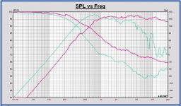
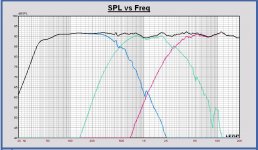
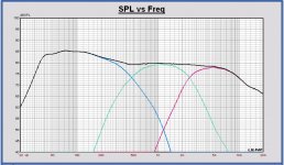
The max SPL of this speaker concept is 112.5 dB at 1m above 40 Hz. So this is at maximum excursion of the woofer above 40Hz. Then the voltage on the speaker has to be 34 Vrms.
Below 40 Hz the excusion becomes higher (plot of it later).
At maximum SPL the maximum excursion of the midrange is 0.52 mm peak at 400 Hz. That is 50 % of its maximum linear excursion.
And at maximum SPL the maximum excursion of the tweeter is 116 um peak at 2500 Hz. That is 50 % of its maximum linear excursion.
A negative point of this LR4 filter at this time is a minimum impedance dip of only 3 Ohm at 38 Hz. I am afraid a serial resistance has to be placed with the first coil of the woofer filter, by using an air coil. Then I can get 4 Ohm as minimum impedance. What is the requirement concerning this minimum impedance value?
I expect that all filter concepts will have this problem.
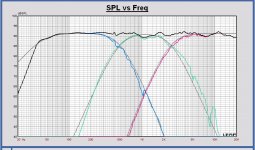
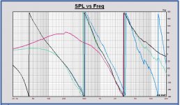
In attach already some plots of SPL, SPL with targets, phase, power, impedance vs. Freq and schematic.
I had to make a comromise for the most flat SPL on axis and the most flat power vs. Freq.
Later more plots vs frequency of excursion, required amplifier power, off axis responses,... and more comments.
This LR4 filter is especially designed for a first check of the speaker behavior.
Later on we can make all kinds of filter concepts, maybe also with the final concept of drivers and cabinet.
Also digital filtering is an option. At this time I can design for miniDSP and Hypex platforms. And calculate biquad coefficients for orhers also.
The max SPL of this speaker concept is 112.5 dB at 1m above 40 Hz. So this is at maximum excursion of the woofer above 40Hz. Then the voltage on the speaker has to be 34 Vrms.
Below 40 Hz the excusion becomes higher (plot of it later).
At maximum SPL the maximum excursion of the midrange is 0.52 mm peak at 400 Hz. That is 50 % of its maximum linear excursion.
And at maximum SPL the maximum excursion of the tweeter is 116 um peak at 2500 Hz. That is 50 % of its maximum linear excursion.
A negative point of this LR4 filter at this time is a minimum impedance dip of only 3 Ohm at 38 Hz. I am afraid a serial resistance has to be placed with the first coil of the woofer filter, by using an air coil. Then I can get 4 Ohm as minimum impedance. What is the requirement concerning this minimum impedance value?
I expect that all filter concepts will have this problem.
In attach already some plots of SPL, SPL with targets, phase, power, impedance vs. Freq and schematic.
I had to make a comromise for the most flat SPL on axis and the most flat power vs. Freq.
Later more plots vs frequency of excursion, required amplifier power, off axis responses,... and more comments.
This LR4 filter is especially designed for a first check of the speaker behavior.
Later on we can make all kinds of filter concepts, maybe also with the final concept of drivers and cabinet.
Also digital filtering is an option. At this time I can design for miniDSP and Hypex platforms. And calculate biquad coefficients for orhers also.
Attachments
-
 Monkey Box SPL LR4 500 - 2500 Hz.JPG145.3 KB · Views: 428
 -
 Monkey Box SPL and targets LR4 500 - 2500 Hz.JPG147.8 KB · Views: 423
 -
 Monkey Box Phase LR4 500 - 2500 Hz.JPG153.7 KB · Views: 423
 -
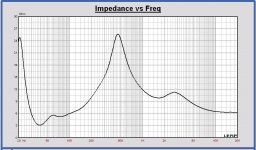 Monkey Box Impedance LR4 500 - 2500 Hz.JPG110.8 KB · Views: 412
 -
 Monkey Box Power LR4 500 - 2500 Hz.JPG144 KB · Views: 123
 -
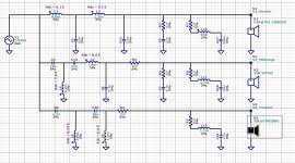 Monkey Box Schematic LR4 500 - 2500 Hz.JPG221.4 KB · Views: 176
Will the tweeter vc be placed "back" a little when using a waveguide, so it is aligned with the mid vc?
Yes, a waveguide would introduce some set back of the tweeter. However, I am not sure which part of the drivers should be aligned. Voice coil, where it meets the dome/cone? The top of the dome? I guess this would need measurements to determine the acousic centres of the drivers.
- Home
- Loudspeakers
- Multi-Way
- Open Source Monkey Box