Time to get to work
Thanks M,
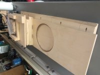
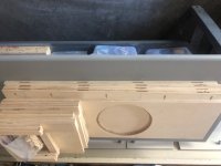
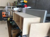
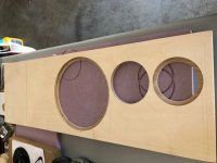
My Monkey tower cabinets arrived this week. Arrived in flat packs. Picks attached. This is a screw and glue operation. The glue is supposedly really good. Loctite PL. Pocket screws and biscuits to hold things in place during build. One pic is a dry fit to check dimensions. All good. Just have to cut speaker holes and figure out how to make sure everything stays square while the glue dries. I'm thinking clamps and some blocking techniques.
I am hoping for suggestions on how to build a square box. All new to me. Trying to avoid the trapezoid shape. I have a large square but I need to hold it square.
Don
Thanks M,
My Monkey tower cabinets arrived this week. Arrived in flat packs. Picks attached. This is a screw and glue operation. The glue is supposedly really good. Loctite PL. Pocket screws and biscuits to hold things in place during build. One pic is a dry fit to check dimensions. All good. Just have to cut speaker holes and figure out how to make sure everything stays square while the glue dries. I'm thinking clamps and some blocking techniques.
I am hoping for suggestions on how to build a square box. All new to me. Trying to avoid the trapezoid shape.
I have a large square but I need to hold it square.Don
Attachments
AWESOME!
My 2 cents. Don't worry so much about square—it's all CNC—mostly square won't be a huge issue I think and all your edges are square and will naturally want to be flat when 90 degrees—plus you have the inner bracing. You also have pocket screws and biscuits there...Meaning... No real benefit to clamping anything. I would suggest clamping when you have situations where setting a pocket screw might shift the joint (biscuits will help things not shift)—this happens all the time with pocket screws since the driving is at an angle. I have a concern about the Loctite PL. It's thick—and not ideal for getting in and around all the biscuits...I used that type of glue for attaching the inner foam. Cleanup will be really really problematic as well since it's polyurethane. I'd suggest using Titebond III—with biscuits and pocket screws you will have zero issues and cleanup will be simple. Of course measuring corner to corner gives you the squareness indication... and you could span diagonally with a clamp to pull square... but with a box that can be hard since you need to address both sides of the box. If it's all a little out... it won't be a big deal when it's all finished (IMO).
Re: the woofer bolts—I used cap heads there as opposed to button head—mostly just a visual thing and I was concerned that the button heads might be too wide for the inset on the rim. Wiggle room good—but really once you route the rabbit—and you have the woofer (or tweeter) sitting in the hole—you will have an easy time marking and drilling for bolts—it's a little tricky with foam inside to get the nuts on from the inside—all doable—with patience. The Volt is FAR harder since you need to map the bolt pattern blindly to the baffle—I gave up using a countersunk head here since then there IS zero wiggle room if you want it perfect. It's also heavy and I found the threads pretty easy to potentially strip while holding it in place from inside. I saw an image of one that had a brass insert that was threaded, perhaps a super current version—mine were directly threaded into the face—could have been on the shelf for a while.
EDIT: Oh—and when clamping—though with screws I don't think it's a concern at all—considering clamping both boxes at once—back to back, if this is clear—requires half the clamps OR you can do both at once. You do need some wax paper in between all glue areas—you don't want to accidentally glue both speakers to each other.
Last edited:
If you include the internal braces while gluing the box up it will automatically be square. Also, I use lots of tape to hold things in place, a bit like a third hand (and fourth and fifth and ...).
Make sure to drill the screw mounting holes for the Volt midrange before gluing the box. Marking and drilling the holes for the Volt in the finished box is a major PITA. I learned this the hard way.
Make sure to drill the screw mounting holes for the Volt midrange before gluing the box. Marking and drilling the holes for the Volt in the finished box is a major PITA. I learned this the hard way.
The cabinet-maker’s trick for precise alignment of a cabinet‘s sides is to use a dowel at the side‘s end (that’s 2 dowels per connection, must be predrilled as precisely as possible), thus the positions of the cabinet‘s parts are defined. Biscuits work „unilateral“ only and the part can move while you’re glueing/joining/clamping…)
If the cabinet will be veneered, you could also use nails to lock the position, but that’s tricky, and they must be removed after the glue has set.
Use the internal bracing as angle, clamp the sides (they‘re forced into a square angle with the braces)
Use the PUR-glue which is awful to work with, but is stronger than the wood itself and thus nearly unbreakable.
If veneer won’t be applied, to avoid a mess on the precious outer sides, use masking tape, mask the part before you connect them. Stick the tape onto the side so that it overlaps, and cut the excess with the sharpest blade you have (razor-blade, cutter or chisel), make sure there’s no overlap into the joint. The expanding glue will flow onto the masking tape… = clean joints!
This project is weird. It seems like I have questions for even the simplest of things.
.......and yet 'God is in the details' as 'myleftear' kindly highlighted.
One of the major mistakes most folks make is not using the proper tightening torque, bolt pattern sequence for the app and unfortunately, driver manufacturers rarely publish it, so usually limited to generic screw/bolt size, thread pitch.
I've long since lost track of how many mysteriously poor performing speakers [especially reflex, compression horn alignments] was due to pinhole leaks around 'crushed' gaskets, bent/cracked frames and the rest around screw/bolt threads screwing into 'T' nuts, threaded inserts.
Don...Be very careful applying any tapes to veneered ply, especially at an edge. Tapes over veneer can and usually will pull grain out—perhaps less of a thing with birch/maple but I've still seen it happen exactly where you don't want it to.... and as I mentioned, for simplicity, since you have butt joints—you may have the best results when final finishing to embrace the multiply and clearcoat it all. Personally I think that would look great. You could also paint wash—also letting the plys be plys. myleftear's sweet advice about registration pins is solid—though if you are clear coating—you will see the pins (and they will telegraph through paint w/o going through a process)—and if you do them blind the expert factor goes WAY up. Any glues left on the surface of ply that aren't removed will not take finish—which is why I was suggesting, due to project size—water based glues will keep you flexible and simplify glue up and you can easily manage squeezeout and excess. I have never seen a failed titebond joint that broke in the glueline—and you have biscuits and a box with lots of support. Just my opinions! Let us know what your final result desire is—we can all keep throwing stuff at you... Sheet veneering of this size isn't for the faint of heart either...paper-backed veneers and proper contact glues would soften the learning curve, but even then... pretty hardcore.
I of course didn‘t consider „grain pull“.
Still, I‘d only use stuff like 3M 244 or maybe 3M 2090, better material. When you remove the tape, always pull it out of the edge (not into the surface) and keep pull it off as „flat“ as possible (this is hard to express…)
And the registration pins naturally should be done blind. Make a reliable drilling template for a precise work!
I'm excited and the anxiety is easing.
I routed the Volt holes and I am amazed how accurate the hole is. The speaker slides in and fits perfectly. Perfect size and perfectly round. Gives me confidence.
Can you tell I'm a novice at the wood working thing? Well, xovers too but I haven't got there yet.
A question. The woofer recess flange(is that what they call it. The part you actually bolt to.) is not that meaty when using 18mm material most commonly used here in the States. Does it need to be reinforced?
Thanks,
Don
Yah! Pics?? I remember having the better part of 7/16" on the woofer flange. Also the design of the cabinet completely secures and reinforces three sides of woofer once the cabinet is together—the sides and bottom of the box being major support structures. Zen Mod made a comment once related to an image I posted about not loving the lack of support—but I think it's just a visual thing—once it's all glued up and you have the interior bracing—it's SOLID—for how compact it is. I do love the look as well. I used washers on the bolts inside, and either nyloc nuts or split ring lock washers as well—can't recall which. Once the whole basket is married with bolts to the wood with the gasket... it's a non issue IMO. 100% awesome.
Thank you. I don't have a bottom there so I think I'll ad another brace to act like one.
My speaker volume is actually 106L and the acoustics are figured at 101L because of volume lost but there are things eating into it like removable back mounting pieces, the additional bracket, etc. All the other stuff was already there. Hopefully Matthias will chime in if he thinks I am going off the deep end. I am trying to maintain all the values that were calculated using 101L volume.
I know there is some tuning available through the base ports. Plural because I have two.
Don
pfarrell,
Sorry, no image. In a nutshell, Everything is the same. Same drivers same location side to side and as measured from the top. Inside height of the volume is 866mm. I then added a bottom and 200mm more for the xovers and then the final bottom. Total length is 1120mm. Everything in 18mm Baltic Birch. It has two rear facing ports 4in diameter and 9+ in long located mid height in the speaker volume and dividing sidewise 1/3, 1/3, 1/3. A couple small tweaks to the xover and that's it.
Doesn't seem like much but you change the volume and everything changes. A lot of really god thinking from a handful of gurus from the original monkey coffin project which I am very thankful for and appreciate of.
My singular graphic is in sketchup and it is not an approved file extension. If you want me to send it to you PM me an email address and I will send it to you.
All this to extend the bass some.
Regards,
Don
My speaker volume is actually 106L and the acoustics are figured at 101L because of volume lost but there are things eating into it like removable back mounting pieces, the additional bracket, etc. All the other stuff was already there. Hopefully Matthias will chime in if he thinks I am going off the deep end. I am trying to maintain all the values that were calculated using 101L volume.
106 vs 101 is a 5% difference. Hardly significant, if you ask me. You're all good.
cutouts and drill outs
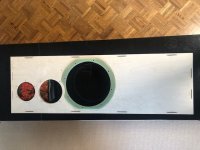
Attached are the driver cutouts and my Volt screw mapping project.
Summary in case it helps somebody. Pics attached.
Cutouts: Two keys. An infinitely adjustable circle jig and cut as many practice holes as you need until you are totally satisfied with the fit. I wanted what I call a slide fit which is really a press fit but it just slides in with little pressure. Thank you pfarrell for talking about the practice part.
The little square paper over the volt speaker is my mapping template. The mounting screws are M5 on a 172mm diameter. I made a template quite easily with a Lietz 45deg drafting triangle. I only use a micrometer to measure since the measurement is digitally read out and I only have to use two points to get a good tic mark. I don't do fractions of millimeters well. My method of being precise. I am drilling 5.5mm holes and will use the counter sink to self center the screws.
I'll let you know how my concept works.
So far so good on the first two holes but am on hold for a portable drill jig because my drill press does not have the "throw to get to all the screw locations.
Sometimes you have to DIY to DIY.
As an FYI, The line approximately 9 inches below the woofer is where the bottom of my tower volume is. The extra space is for two floors and the xover space. I took them out of the driver section but did not want two more boxes (or one more).
Regards,
Don
Attachments
I'll bite... subjective style.
Let's first acknowledge the potential of the idea that a speaker is mostly the room it's in?
Here's the speaks I've had in my space (and still use elsewhere) previous to OSMB:
— B&W CM1 (Very small, but actually really impressive, loads of bass if you can believe it, not super efficient)
— Omega Super 3 HO (Had a personal conversation with the builder in CT, these were about efficiency when I first started building NP amps, if I hadn't decided to build speaks—adding a sub would have been something to try)
Speakers I have heard in a very controlled environment with NP equipment and similar sources that I use in my own setup (i.e. vinyl):
— Snell E/III
— Sony SS-M7
Subjectively in the list above—the OSMB are the equal of the Snells with the other speakers falling short for various reasons....I would say from memory that the OSMB have more of everything the Snells had. Completely not an A/B eval however, and the Snells opened my eyes/ears when I was new to all of this.
I'd say that I can't find a reason to not build the OSMB, but it's my first experience with a 3-way. A concept that seems to just make sense to my brain.
I'm beginning to see speakers like I view vinyl cartridges—there are lots of options and no one-size-fits-all solutions, downstream variables do play a part—and it's just too much fun to have several options.
In short—nothing ventured nothing gained—and I can't for a second imagine you wouldn't find value in the project.
@don—missed that post above—looking GREAT!
dry fit
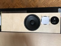
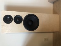
Attached are a couple pics of my front baffle with speakers dry fit. Tedious to get it right but it all worked.
The green ring on the woofer cutout is 1/8 in G10. It is really tough stuff and great for backing plates. Maybe overkill but the bottom of the speaker volume is further away on my tower so I opted for the reinforcement.
Now to assemble the cabinets.
My plan is to finish (stain, paint, whatever) the cabinets before I start to put everything together. The wood is 18mm baltic birch.
pfarrell, hopefully you are on frequency. I think you did a base coats clear coats type of finish. I have your info on the clear. What/how did you do the color coat?
Was it basically a paint or stain rubbed or brushed on?
Thanks to all who posted. Especially M who has been relentless with answers.
Don
Attachments
Oh man! Super exciting Don. Looks great. I see you opted for the "off center non-12 o' clock" woofer bolt alignment. That will make it easier inside.
Re: finishing. I went perhaps a bit rogue here—but it's based on years of experimentation making photography backdrops for our own professional purposes. I also involved my wife in the process of the color/design in order to gain support for a project that, well, wasn't really optional in my opinion! At one point she had no less than 18 swatches of whites painted on our walls deciding which white we'd use in the house. I used the exact Benjamin Moore Regal Select paint on the speakers as we used on our walls (Chantilly Lace) OMG. BUT I thinned every coat, and went through the usual process of knocking down the grain/flattening brush strokes each coat, and filling voids/blemishes. I did this process for about 10 coats, building thin layers up. Then I used a poly satin clear coat, for an additional 3 coats. All water based. What you end up with is a decidedly organic looking finish—but very professional looking as well. It's not about some perfect non-orange-peel high gloss candy coated finish. What I did has a different kind of depth—probably a direct result of so many coats. I let the plys telegraph a bit on the various edges and didn't worry about trying to make them completely go away. (to do that BTW involves Bondo in my experience.)
Re: finishing. I went perhaps a bit rogue here—but it's based on years of experimentation making photography backdrops for our own professional purposes. I also involved my wife in the process of the color/design in order to gain support for a project that, well, wasn't really optional in my opinion! At one point she had no less than 18 swatches of whites painted on our walls deciding which white we'd use in the house. I used the exact Benjamin Moore Regal Select paint on the speakers as we used on our walls (Chantilly Lace) OMG. BUT I thinned every coat, and went through the usual process of knocking down the grain/flattening brush strokes each coat, and filling voids/blemishes. I did this process for about 10 coats, building thin layers up. Then I used a poly satin clear coat, for an additional 3 coats. All water based. What you end up with is a decidedly organic looking finish—but very professional looking as well. It's not about some perfect non-orange-peel high gloss candy coated finish. What I did has a different kind of depth—probably a direct result of so many coats. I let the plys telegraph a bit on the various edges and didn't worry about trying to make them completely go away. (to do that BTW involves Bondo in my experience.)
@pfarrell,
As usual, very helpful. Thank you. I am actually kind of surprised after all those coats, albeit thinned, that there is still some read through. Interesting.
Re the woofer bolt alignment - form follows function. I kind of wondered when I got into the build why it was designed so tight driver wise. Maybe M will chime in and give us the background. Anyway, I am trying to build it as accurately as possible and change is not on the table.
I will keep posting and asking questions as I couldn't do this on my own. Thanks again.
R,
Don
Re the woofer bolt alignment - form follows function. I kind of wondered when I got into the build why it was designed so tight driver wise. Maybe M will chime in and give us the background. Anyway, I am trying to build it as accurately as possible and change is not on the table.
I wanted the drivers close to each other to reduce vertical dispersion, and to make them fit on the OSMC front baffle. I designed it such that the woofer screw holes would fit around the magnet of the midrange, even if the screw holes would be arranged "horizontal" as shown here.
- Home
- Loudspeakers
- Multi-Way
- Open Source Monkey Box