I have some doubts about the abrupt changes of the curve slopes outband. Some impact on the time response of the filter can be expected, I don't like so much.
Well, I put in the coefficients to the miniDSP. No sound... after thinking about this a bit more, I realised the biquads I get from my tool fit nicely to the target curves, but they are not stable. I don't know enough about designing IIR/biquad filters to avoid this. Anyone?
Is there a better way to determine the required DSP coefficients for a given design of an analog x-over circuit to be tested using a miniDSP???
Here a digital design of a EL3 500-2500 Hz with biquads, ready to copy in miniDSP.
Woofer filter 3 biquads, midrange filter 4 biquads and tweeter filter 3 biquads. Very easy drivers.
I suppose the miniDSP 2 x 4 HD is running also at 96 kHz? Otherwise I have to change the coeffs.
I did a test in the miniDSP software plug MiniDSP-2x8 Version 1.12, and it works.
Don't forget to set the AC offset in miniDSP, because I have done this design with minimum phase curves now. So you have to set the offsets.
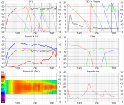
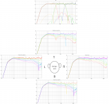
In attach the SPL and xo transfer plots of this design.
Success!
Woofer filter 3 biquads, midrange filter 4 biquads and tweeter filter 3 biquads. Very easy drivers.
I suppose the miniDSP 2 x 4 HD is running also at 96 kHz? Otherwise I have to change the coeffs.
I did a test in the miniDSP software plug MiniDSP-2x8 Version 1.12, and it works.
Don't forget to set the AC offset in miniDSP, because I have done this design with minimum phase curves now. So you have to set the offsets.
In attach the SPL and xo transfer plots of this design.
Success!
Attachments
Don't forget to set the AC offset in miniDSP, because I have done this design with minimum phase curves now. So you have to set the offsets.
In attach the SPL and xo transfer plots of this design.
Success!
Aaahhhhhhh! Thanks, that works now. It's amazing how easy it is to follow your earlier description of the the elliptic filters sound in comparison to Butterworth and Linkwitz-Riley. EL3 sounds very dynamic, in an easy way.
I will listen to this for a bit, and take some measurements to see how well it really works, and where/how it needs tweaking.
Oh, and, aehm, I don't know where/how to set the offsets...
For the AC setting, for each output in the output window you can set the delay in ms at the bottom of that output window.
For the monkey box, delay midrange = 0.11 ms and delay for tweeter 0.08 ms. Woofer 0 ms of course.
Great that you already recognize that typical sound of the elliptical filters.
And that with a mono set") .
.
It depends on your taste what you like in a speaker, the elliptical filters give a lot of life experience and personally I like that.
For the monkey box, delay midrange = 0.11 ms and delay for tweeter 0.08 ms. Woofer 0 ms of course.
Great that you already recognize that typical sound of the elliptical filters.
And that with a mono set
.It depends on your taste what you like in a speaker, the elliptical filters give a lot of life experience and personally I like that.
For the AC setting, for each output in the output window you can set the delay in ms at the bottom of that output window.
For the monkey box, delay midrange = 0.11 ms and delay for tweeter 0.08 ms. Woofer 0 ms of course.
Ok, found it. But aren't we trying to simulate the analog EL3 filter circuit? This does not have any allpass/delays. Shouldn't the delays remain at 0 in the DSP settings?
It would be good to have some way for me to tweak those biquads such that they remain in sync with an analog filter that we can actually build. What's the best way to do this?
I took Byrtts Vituix project file from post 544 and replaced the measurment data with those from post 576. Then I started having fun with the values of the x-over components. The result is attached.
What do you think?
How can I get this into the miniDSP (filter curves attached)?
What do you think?
How can I get this into the miniDSP (filter curves attached)?
Attachments
But aren't we trying to simulate the analog EL3 filter circuit? This does not have any allpass/delays. Shouldn't the delays remain at 0 in the DSP settings?
It would be good to have some way for me to tweak those biquads such that they remain in sync with an analog filter that we can actually build. What's the best way to do this?
Yes of course, to make a digital version first as a model for the passive filter you have to set the delays to zero. To make it exactly the same will be diificult, because in a passive filter there will be the extra interaction with the impedances.
Why not design on the same filter targets in both the digital and analog version, IMO the best way to do and they will be very simular.
I took Byrtts Vituix project file from post 544 and replaced the measurment data with those from post 576. Then I started having fun with the values of the x-over components. The result is attached.
What do you think?
How can I get this into the miniDSP (filter curves attached)?
Think looks you did a good job tweaking XO components using post 576 measurements, so did Paul on initial component values for on axis he had there.
That said if you happy of reality prediction used for post 576 measurement thats it, if it happen you take other measurements down the road suggest set measurement chain to its highest possible samplerate and let frd files resolute up to at least 23kHz area or more that M23 should be capable of, often the true or best HF tail can mean alot and area at low end can improve too.
Paul has package to get those filter curves into biquads.
I took Byrtts Vituix project file from post 544 and replaced the measurment data with those from post 576. Then I started having fun with the values of the x-over components. The result is attached.
What do you think?
How can I get this into the miniDSP (filter curves attached)?
I don't see any filter targets? While tweaking components, it is important to look also to the deviation from the targets. Driver filter targets are theoretical and have a relation to each other, because they use polynomials with a same behavior, also w.r.t. timing. Changing components without monitoring the deviation from target, will lead to worse matching between the filtered drivers. Not my preferred way of designing...
Hahah! That's a big "party hump" Matthias
Have you listened to it using just slope eq? Probably sounds very "fun", it's probably a really good match for the MonkeyBox.
Not sure what you're referring to. The general trends of the SPL curves and filter curves are very similar to Pauls initial EL3 design. I just tweaked the values of the x-over parts to get a smoother off-axis response, trying not to screw up the on-axis curve too much. No, I have not listened to this "version" since I don't have the corresponding filter implementation for the DSP.
Yes of course, to make a digital version first as a model for the passive filter you have to set the delays to zero. To make it exactly the same will be diificult, because in a passive filter there will be the extra interaction with the impedances.
Why not design on the same filter targets in both the digital and analog version, IMO the best way to do and they will be very simular.
That was exactly my idea -- design an analog filter (in Leap/Vituix/whatever), take their transfer curves (voltage at the driver terminals), fit a biquad filter to these curves, and test the filter like this before actually building the analog filter circuit. This means we have have to take into account the driver impedances in the simulation of the analog filter circuit (which we did so far) in order to obtain the true filter transfer curves (voltage at the driver terminals) of our analog filter design. If we use an amplifier with a high damping factor in the active/DSP setup (which I do), the driver impedances do not affect the voltage at the driver terminals (=voltage at the amplifier output). We therefore "just" need to implement the filter transfer curves of the analog filter in the DSP without any change. The trick is to implement an accurate "copy" of the analog filter curves in the DSP. I simply don't know how to do that, so I am hoping someone else can do this (in Leap?).
Thinking about this, I am sure there must be some mathematical way to translate the individual parts of the analog filter (L/C/R combos) into biquads. I just don't have the necessary EE/DSP theory background...
In Leap it is very simple, importing the electrical xo transfers of the analog filter, adapt the schematic with analog functional blocks in Leap to fit on those transfers, bilinear transform on the final analog blocks and there are the biquad coëfficiënts.
If the analog and digital version are designed on the same filter targets, there is no need for such cross check. They will perform the same.
If tweaking is not done on filter targets, than you have to do the procedure like described to fit the analog and digital design, of course.
If the analog and digital version are designed on the same filter targets, there is no need for such cross check. They will perform the same.
If tweaking is not done on filter targets, than you have to do the procedure like described to fit the analog and digital design, of course.
I don't see any filter targets? While tweaking components, it is important to look also to the deviation from the targets.
Is this possible with Vituix?
Can you still make a biquad version in Leap using the filter transfer curves in my previous post?
Is this possible with Vituix?...
Its not called target but rightclick in SPL plot gives possibilty of up to two overlays at a time, alternative for using visual target curves is VituaixCAD can be open multiple of times so now open a new session and setup three directly wired drivers where each driver have Paul's three bandpass targetfiles linked and in full screen mode one can toggle between the two open VituixCAD sessions to see if your curves line up or not to target.
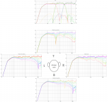
Below is using the up to two overlays in SPL plot, left one as is with post 576 handcrafted predictions of measurements and right one is with tweaked components. Sure horizontals plus power response and directivity index improve with tweaked components, quistion is if you happy about how true those edited measurements of post 576.
Attachments
Last edited:
Below is using the up to two overlays in SPL plot, left one as is with post 576 handcrafted predictions of measurements and right one is with tweaked components. Sure horizontals plus power response and directivity index improve with tweaked components, quistion is if you happy about how true those edited measurements of post 576.
My first priority is the acoustic result of the entire system. Matching the curves of each driver to the filter target curves is second priority. As far as I can tell, the revised filter does both (with slightly lower x-over frequencies, but the curve/slope shapes match up quite nicely if you ask me).
Now I need to get this into the miniDSP so that I can ask my ears and my microphone about their opinions.
I am working at it...Now I need to get this into the miniDSP so that I can ask my ears and my microphone about their opinions.
I can see you have chosen for a slow fall off to high frequencies in the tweaked version. I can understand why, it is a choice.
I will use the voltage xo transfers of the tweaked version as a target for the digital design.
...Now I need to get this into the miniDSP so that I can ask my ears and my microphone about their opinions.
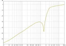
Okay here is a trial for your component tweaked version, we can start see if it works for HF band and if it does i upload for MF/LF bands later. Its a bin-file to load into FIR section of miniDSP that replicate the electric filter from the component tweaked version, so what you shall do is clear or bypass all biquads or settings into the PEQs and Crossover sections and load that bin-file into FIR section, its a pure IIR correction and to test it works without damage anything suggest start make a sweep and measure the electric RCA output signal looks something like below curve.
If this FIR loading works i explain later and you can diy in a few minutes per passband.
Attachments
Last edited:
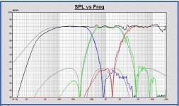
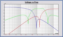
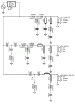
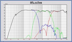
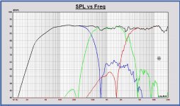
Here the digital design in Leap of the tweaked EL3 by Matthias
In the plots:
- schematic tweaked passive EL3 xo
- SPL tweaked passive xo
- SPL tweaked digital xo
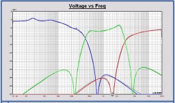
- voltage tranfers digital xo (color) and the transfer targets of passive xo (grey)
I did my very best for a fit as good as possible.
Success with it Matthias!
Edit: I just checked the passive xo component values again, I used a wrong value for a coil in the tweeter xo, 360 uH instead of 390 uH.
This will give a minor change. I think it is ok for a test now.
In the plots:
- schematic tweaked passive EL3 xo
- SPL tweaked passive xo
- SPL tweaked digital xo
- voltage tranfers digital xo (color) and the transfer targets of passive xo (grey)
I did my very best for a fit as good as possible
.Success with it Matthias!
Edit: I just checked the passive xo component values again, I used a wrong value for a coil in the tweeter xo, 360 uH instead of 390 uH.
This will give a minor change. I think it is ok for a test now.
Attachments
-
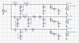 20190109 MonkeyB schematic tweak EL3.JPG227.5 KB · Views: 226
 -
 20190109 MonkeyB SPL tweak EL3 passive.JPG151 KB · Views: 216
 -
 20190109 MonkeyB SPL tweak EL3 digital.JPG187.8 KB · Views: 88
 -
 20190109 MonkeyB Voltage transfer digital EL3.JPG145.2 KB · Views: 80
 -
V66 MonkeyB Dig tweak EL3 450-2500 biquad coeffs.zip1.6 KB · Views: 39
Last edited:
Okay here is a trial for your component tweaked version, we can start see if it works for HF band and if it does i upload for MF/LF bands later. Its a bin-file to load into FIR section of miniDSP...
Hmm, I am not sure the FIR apporach is right to simulate a real-world analog filter. Does the phase response match? Usually, IIR filters are used to simulate analog filters, whereas FIRs don't have analog implementations.
- Home
- Loudspeakers
- Multi-Way
- Open Source Monkey Box