Take a FFT window of 30 ms for example. Just to see if there is a low frequency SPL improvement.
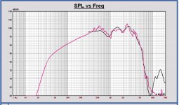
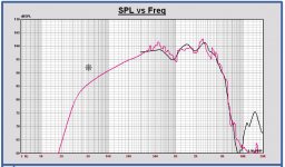
In attach the simulation (red) vs. the measurement + 1.5 dB (black) for midrange and woofer.
But where to splice, especially for the midrange. It looks like there is a lot of smoothing due to the 6 ms FFT window. But not sure of that...
Indeed the simulation fits well, just that bafflestep issue, I have to solve that.
Attachments
Hey I just realised the fundraiser for the Monkey Coffin prototyping was successfull! Someone donated the missing amount to fill up the bucket to the CHF 400 mark! Thank you very much!
I have spent about 10% of the money for the prototype box, so we still have a lot for x-over parts.
Wow that is good news!
I was wondering if there are people that have plans to built this speaker now or in the future...
It should be nice to get some feedback of them.
Take a FFT window of 30 ms for example. Just to see if there is a low frequency SPL improvement ... It looks like there is a lot of smoothing due to the 6 ms FFT window. But not sure of that...
Yes, the time gating smears out the information at the low end. Here's a ZIP with SPL curves from a 30 ms gate time, with different smoothing.
Attachments
Much better! We come closer and closer to the simulation.
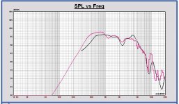
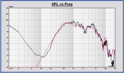
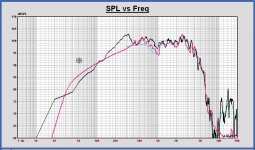
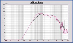
Look in the plot, simulation in red, 6ms gate time in green and 30ms gate time and extra smoothed in black. I have applied two times 1/4 octave extra smoothing in Leap.
All the different smoothing versions you posted have exactly the same SPL, strange...In the second plot I have added it in blue.
You see a SPL dip at 600 Hz which is not in the simulation. Maybe caused by the concave woofer cone very close to the midrange, which is not in the simulation.
I think all can be further improved maybe by a even longer FFT window. Till now I cannot read the impulse response in Leap. I'll look for that later.
If you will do now Matthias with the longest gate time with best SPL results. And no smoothing, I can do that in Leap for the best result.
Can you also do these long FFT's for tweeter also? And also a trial for the woofer to compare the bafflestep response also. Thanks.
Attachments
All the different smoothing versions you posted have exactly the same SPL, strange...
Not sure why this would be strange. I'd expect the SPL to be the same, just smoother curves with more smoothing.
I think all can be further improved maybe by a even longer FFT window ... If you will do now Matthias with the longest gate time.
Ok, I exported the FRDs without any smoothing and taking the full length of the data in the TMD files (100 ms), for the tweeter, midrange and woofer.
Attachments
Becoming ok now. I have only applied a 1/12 octave smoothing now.
I hope reflections are averaged out, it looks like.
Splicing can be done at 240 Hz if we are sure of this SPL response? I think it is...
Where is the start of the FFT placed now? I see all phase information is lost due to a lot of delay. It is best to set the start of the gate time just before the impulse start.
I can do a minimum phase transform on the SPL, but I prefer to use the measured phase.
I take a look now to tweeter and woofer gate time 100ms.
And try to import impulse myself, not found yet.
Attachments
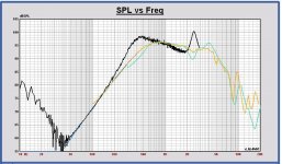
Same for woofer.
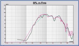
Simulation in red, FFT 100ms 1/12 octave smoothed in black, FFT 6ms smoothed in green.
To be sure of this way of processing we should be able to do a cross check with an anechoic measurement. This is the first time I try it this way, I have always used outdoor measurements for my own projects.
I am wondering if we don't add some random noise to the measurement, because reflections are not averaged perfectly.
But the fit on the simulation looks good, maybe the added noise is minimal.
What do you think?
Looking to the curves, for the woofer we can do splicing at 400 Hz.
Strange is the peak at 300 Hz, I don't understand exactly...
Same remark for the phase, no info above 1 kHz.
Attachments
Last edited:
Where is the start of the FFT placed now? I see all phase information is lost due to a lot of delay.
The phase in the data files is the full phase ( = excess phase + minimum phase). You can just subtract the excess phase due to the "flight time" from the driver to the microphone, or just calculate minimum phase from the SPL response. I guess Leap will do either of these -- let me know if you want me to do this in MATAA.
I don't fully understand your "random noise" argument. Where would the "random noise" come from?
Longer gate times do of course result in more wiggles due to inclusion of echoes (not random!), and one needs to apply a lot of smoothing to remove these wiggles. What you get from a long gate time (and smoothing) is the in-room response. In my experience, with a lot of smoothing, this can be surprisingly similar to the anechoic SPL response -- except maybe at bass. The approach can indeed be useful to guide your choice of where/how to do the splicing with the theoretical bass response from the Leap model, if you manage to stay away from the bass region where things go off.
Last edited:
Subtracting the excess phase is no option. Because of the large excess delay, there is no phase resolution anymore above 1 kHz.
But I can use again your 6 ms FFT. There I have to compensate for about 520 us.
I prefer to use measured phase above splicing if possible, because in the driver stop band there is no minimum phase behavior sometimes.
But I can use again your 6 ms FFT. There I have to compensate for about 520 us.
I prefer to use measured phase above splicing if possible, because in the driver stop band there is no minimum phase behavior sometimes.
I don't fully understand your "random noise" argument. Where would the "random noise" come from?
Longer gate times do of course result in more wiggles due to inclusion of echoes (not random!), and one needs to apply a lot of smoothing to remove these wiggles. What you get from a long gate time (and smoothing) is the in-room response. In my experience, with a lot of smoothing, this can be surprisingly similar to the anechoic SPL response -- except maybe at bass. The approach can indeed be useful to guide your choice of where/how to do the splicing with the theoretical bass response from the Leap model, if you manage to stay away from the bass region where things go off.
Look to what I see in the Clio system with an other SPL measurement.
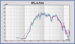
In the first plot FFT 8ms without reflections and FFT 30 ms with reflections
In the second plot FFT 8 ms without reflections and FFT 30 ms with reflections and 1/3 octave smoothed.
You can see a SPL increase around 1 kHz in a wide band.
By adding random noise I mean the mean averaged value of the reflections during the gate time which is not zero.
And I see the same kind of SPL differences appearing in your measurements with longer gate time and smoothed.
No, it is not correct.
Edit:
Thinking about this longer. By increasing the gate time, the measurement becomes more and more a half plane measurement.
That can explain the SPL increase. But the ground reflections will affect also the SPL shape probably??
Attachments
Last edited:
You can see a SPL increase around 1 kHz in a wide band.
Aha, ok, that's the echoes bouncing back from the room, adding to the sound energy that is recorded at the microphone.
Matthias,
The problem I have is how to splice data and in a correct way. For this project I like to be sure of all that it is correct within 1 dB.
Look to the woofer and midrange plots, simulation in red and measurement +1.5 dB in black.
For the woofer a splice frequency at 350 Hz is ok I think.
But what about the midrange? That is my problem now.
Attachments
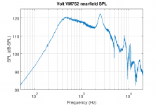
I guess an nearfield measurement of the midrange might be useful. Theory says that nearfield SPL curves work up to fMax = 5475/a, where a is the cone radius in cm. If this is correct, we'll get useful nearfield data up to about 1.5 kHz for the VM752. The waveguide might interfere with this a bit, but... I'll give it a try.
Edit: Done! Nearfield measurement of the VM752 is attached.
Edit: Done! Nearfield measurement of the VM752 is attached.
Attachments
Last edited:
Here the nearfield measurement (scaled) in black, the infinte baffle response of datasheet in yellow (equal to Leap infinite baffle model) and the measurement in Monkey box in green.
I don't understand this, dome radiation looks complex...
Yes, a good test can be to simulate a 3 inch dome on the Monkey Box baffle with other bafflestep simulation software and apply on the current infinite baffle response (not the nearfield). And compare with measurement and Leap simulation.
I don't have immediately such other tool. You Matthias?
Other test can be SPL at 50cm and at 25 cm on axis, to understand the nearfield response better.
Attachments
Last edited:
This 5db+ peak at 2.5Khz ( present in the nearfield measurement ) disappears to differing degrees with other forms of measurements.
In fact it turns into a notch with most other measurements, which is interesting unto itself.
Does anyone else think that the peaks attenuation is controlled by the dimensions of the cavity built into that concave horn?
Smoothing out the horn cavity with modelling clay would be one way to find out.
")
I did use Jef Bagby baffle edge diffraction calculator for the Volt midrange in the Monkey Box baffle and compared with the Leap simulation.
Little difference but very comparable.
Edit: maybe we should splice data for the midrange at 1kHz for now?
And assuming the measurement with gate time of 6 ms has some smoothing effects below 1 kHz?
To make some further progress now... we can check later on again.
From my side I have some plans to check the Leap diffraction simulation anyway.
Attachments
Last edited:
I think the baffle diffraction signature will be most accurate and useful below the diffraction peak. Which is fine, because ideally you are splicing fairly low. The nearfield measurement itself is not that accurate at higher frequencies.
It is well laid out in "Measuring SPL" here: SoundEasy Design Guide This is for Soundeasy, but the principle is exactly the same regardless of software. It's a method that works great, better IMHO than other competing methods when you balance all the pros and cons of each (ungated, smoothed in-room, or variable gating, for example).
It is well laid out in "Measuring SPL" here: SoundEasy Design Guide This is for Soundeasy, but the principle is exactly the same regardless of software. It's a method that works great, better IMHO than other competing methods when you balance all the pros and cons of each (ungated, smoothed in-room, or variable gating, for example).
Jeff also makes a blender software that has each step in the process. Personally I don't care for blending,I think it should be a hard cut with Hilbert-Bode Transform applied, but you might find the tradeoffs acceptable, and it might have provision for a hard cut if you don't.
- Home
- Loudspeakers
- Multi-Way
- Open Source Monkey Box