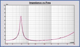
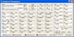
Changing BL in a model for the best fit on a measured curve goes very hard w.r.t. TSP values.
If I use the fit like in the plot with BL=13.5 N/A and Qms = 5.9, the calculated Qes becomes 0.43, conform your results
That is the reason I am asking for the measurement conditions, because a TSP calculation is so sensitive.
The Leap TSP calculation is correct. It is conform the Clio TSP calculation too, I have checked that earlier.
Attachments
Last edited:
Changing BL in a model for the best fit on a measured curve goes very hard w.r.t. TSP values.
If I use the fit like in the plot with BL=13.5 N/A and Qms = 5.9, the calculated Qes becomes 0.43, conform your results
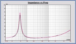
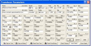
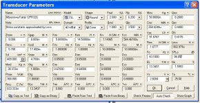
Hmm, the LEAP screenshot says Qes = 0.463 (not 0.43), and the peak of the model curve is a bit wider than the measured peak. Can you try Qes = 0.43 and Qms = 5.7 to see if our calculations are consistent?
A mistake from my side sorry.
If I force Qes to be 0.43, the BL becomes 14 N/A and the impedance peak becomes wider. For the best fitting not the right direction (in Leap).
If I force Qes to be 0.43, the BL becomes 14 N/A and the impedance peak becomes wider. For the best fitting not the right direction (in Leap).
Attachments
Sorry, took me a while to catch up. I wanted to understand what's going on with the Thiele Small parameters of the Faital driver and get things right, so I determined the Mms (cone mass incl. air load) using the "added mass" method. The results were 50.8 g (driver A) and 48.7 g (driver B), nicely consistent with the datasheet value of 51.4 g. This means the slightly high resonance frequencies I found earlier corresponded to a lower Cms value of about 0.23 mm/N instead of 0.28 mm/N in the datasheet. Was the break-in not enough to loosen all the mechanical parts? Ok, more break-in, and harder than before (24h @ 25 Vrms). Sure enough, the resonance frequency went down after that... I continued the procedure, but the resonance frequency remained constant after another 12h. I am assuming that driver is now stable, break-in done.
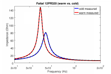
I let the driver cool down for two hours in the cold workshop (remember: no heating, and winter is close. I'd estimate about 10 deg.C or so). I first measured the impedance curve of the driver in "cold" condition, and then again after heating the surround with a heat gun (no, it was not hot, but a bit warmer than before). The resulting curves are attached (dashed lines are model fits).
Parameters are:
"cold":
fs = 46.100
Qes = 0.46000
Qms = 6.4000
"warm":
fs = 40.100
Qes = 0.42000
Qms = 11
mean values:
fs = 43.1 (datasheet: 7.2)
Qes = 0.44 (datasheet: 0.39)
Qms = 8.2 (datasheet: 7.8)
Qts = 0.42
Using these mean values and Mms = 50.8 g:
Cms = 0.27 mm/N (datasheet: 0.28 mm/N)
Vas = 91.1 L (datasheet: 94.8 L)
These results are pretty convincing to me that the Faital 12PR320 datasheet is ok")
The Faital it is!!!
I let the driver cool down for two hours in the cold workshop (remember: no heating, and winter is close. I'd estimate about 10 deg.C or so). I first measured the impedance curve of the driver in "cold" condition, and then again after heating the surround with a heat gun (no, it was not hot, but a bit warmer than before). The resulting curves are attached (dashed lines are model fits).
Parameters are:
"cold":
fs = 46.100
Qes = 0.46000
Qms = 6.4000
"warm":
fs = 40.100
Qes = 0.42000
Qms = 11
mean values:
fs = 43.1 (datasheet: 7.2)
Qes = 0.44 (datasheet: 0.39)
Qms = 8.2 (datasheet: 7.8)
Qts = 0.42
Using these mean values and Mms = 50.8 g:
Cms = 0.27 mm/N (datasheet: 0.28 mm/N)
Vas = 91.1 L (datasheet: 94.8 L)
These results are pretty convincing to me that the Faital 12PR320 datasheet is ok
The Faital it is!!!
Attachments
Last edited:
Hi Matthias,
Good job, your way of working gives a lot of trust.
I have no experience with drivers with such suspension, I don't expect these differences with a rubber surround.
I recently purchased some Eton 11-212, they were almost conform datasheet with the first measurement and also after some break in, but not done so long as you do.
The difference of the TSP cold - warm and before - after break-in are high. Is this normal for such suspensions?
In attach the adapted Faital Leap model with your last mean values.
Good job, your way of working gives a lot of trust.
I have no experience with drivers with such suspension, I don't expect these differences with a rubber surround.
I recently purchased some Eton 11-212, they were almost conform datasheet with the first measurement and also after some break in, but not done so long as you do
.The difference of the TSP cold - warm and before - after break-in are high. Is this normal for such suspensions?
In attach the adapted Faital Leap model with your last mean values.
Attachments
A few comments
It has been interesting to observe this projects evolution.... group and individual decisions co-mingled.... many excellent observations and contributions. But for the sake of, well, practicality, and, god do I say it, profit, I am also developing a commercial version, more or less of what this thread has been chasing.
Up front, NO, I am not directly using any of the information developed on the tread. My inspiration, motivation, is to create, or maybe, recreate the best of four past worlds (designs). A combination of all the best attributes of the second generation AR3A, the resolution of the Yamaha NS-1000 series, the forgiving and musical qualities of the Dynaco A-25 and the dynamics and efficiency of the JBL L100. And do it in a similar, more or less sized enclosure for an averaged inflation adjusted cost that would be an average of all of the previous four designs. And use current production drivers. Enclosure max dimension are 14.5" W, 28" H and 13" D. Net internal volume for the woofer including adjustments for driver parasitic volumes and crossover volume would be in the 58-64 liter area.
Assuming it is 1970 all over again, the above systems sold from roughly $120 - $285 each. So we are looking for an average cost around $210 - $215 per speaker in late 60's to early 70s' in U.S. dollars. Using Bureau Of Labor Statistics data, each speaker would be valued around $1,430 or so. Or, $2,860 retail a pair. That is our retail target, and, can we realistically do it?? BTW, I am fudging on the Yamaha. Depending on the cabinet this speaker cost topped $500 each! Beryllium drivers are not, and were not cheap! So the original costs figures I am using are conservative.
To be fair, we set the design to include the following minimums: Three way with a 12" woofer, mid range type and size to be determined and a 1" give or take dome tweeter. The system should have an honest efficiency around 90 dbw half space, an anechoic F3 in the mid 30's. Power handling is in the 100-150 watt area. Max clean acoustic output per pair will approach 1 acoustic watt from 50 Hz up. Being a Monkey box, it will require a stand of some sort. Stand height will place the average of the mid range and tweeter axis in the upper 30" area. This is appropriate for a typical seated listener. Tonal balance assumes the speaker baffle face is forward of the rear wall 24"- 36". Also assuming a mid grade furniture quality cabinet exterior. Better than the standard of the day, but not the wonderful rosewood Yamaha!
The first decision is seal or ported? I am going with sealed. Much more tolerant of driver spec variances and can handle over power low frequency abuses. Mid range would be a larger dome. Tweeter the same. Preserves enclosure internal volume. Simplistic. Consistent. A Kiss design. Which is why AR, Advent, KLH, and to some extent Dynaco stuck with this as a basic design.
As is ALWAYS the case, viability of the design comes down to crossover. A LOT of work and time to get is as good as it can get without spending heroic amounts of money and complexity.
It will be fun to watch where the Monkey Box thread goes and the results of same! Good luck!
Next steps
The Volt midrange drivers will not arrive before mid November (seems like Volt is making the just for me...), and I will be away for real-life work anyway. This means the Monkey Coffin design may not get much further in the meantime. It will kick back to life once the Volts are here and the measurements will tell us what kind of dispersion we are looking at.
The Volt midrange drivers will not arrive before mid November (seems like Volt is making the just for me...), and I will be away for real-life work anyway. This means the Monkey Coffin design may not get much further in the meantime. It will kick back to life once the Volts are here and the measurements will tell us what kind of dispersion we are looking at.
Matthias, once you have installed your IEC baffle, you will see it will become the best investment till now in your audio hobby.
That is my experience after instaliing and using mine.
You will be able to measure yourself the infinite baffle response apart from the enclosure.
And in my case I need these for making driver infinite baffle models in Leap.
That is my experience after instaliing and using mine.
You will be able to measure yourself the infinite baffle response apart from the enclosure.
And in my case I need these for making driver infinite baffle models in Leap.
I do not think people understand the actual need for some small funding when developing this prototype. Remember, the money is not for drivers, they are for wood and other materials that are needed for the sake of prototyping, measurements, and further modification/adaption after measuring, then repeating the process until the design is deemed good enough.
I've already given 50 euros, not flush with cash at the moment, but I will add another 25€.
Edit:
Have just added another small donation.
I've already given 50 euros, not flush with cash at the moment, but I will add another 25€.
Edit:
Have just added another small donation.
Last edited:
Apologies if you have already mentioned this elsewhere, but do you have a breakdown of the expected costs for this project?
$550+ AUD (400CHF) seems a bit high for 'wood and other materials'.
I feel you might get more donations if the costs were broken down such as:
I need:
x sheets of ply at xCHF;
x meters of enamelled copper wire for x-overs at xCHF...
etc..
$550+ AUD (400CHF) seems a bit high for 'wood and other materials'.
I feel you might get more donations if the costs were broken down such as:
I need:
x sheets of ply at xCHF;
x meters of enamelled copper wire for x-overs at xCHF...
etc..
This is not about building a finalized kit. I'll be messing around with a prototype, and try to tweak it as much as possible. It simply makes no sense to specifiy the length of enamelled wired I am going to need for this. See here for a coarse description of what's on the agenda.
I'll need money for wood, stuffing materials, and mostly for various x-over parts. Take a look at Pauls draft circuit, which has quite a few parts. This can be expected to require a number of modifications and different parts.
I'll need money for wood, stuffing materials, and mostly for various x-over parts. Take a look at Pauls draft circuit, which has quite a few parts. This can be expected to require a number of modifications and different parts.
This is not about building a finalized kit.
I understand that.
But what made you decide 400 francs was the figure you needed? Surely you made some rough estimations of the quantity of materials needed?
It simply makes no sense to specifiy the length of enamelled wired I am going to need for this.
Again, I understand - I was giving you an example. It is simple project management / estimation to figure out how much a unit is likely to cost rather than pluck a random number.
Do you think you might need 50m or 10km of ECW? Do you think you might need 10 sheets of ply or 100? Do you think you will need to build 10 prototypes or 50? etc etc.
I'm interested in this project and would donate to help get this going but it is hard to justify without more information.
Sorry for my reaction, avtech23, but I cannot appreciate your comments on the budget.
Matthias and other people are putting a lot of efforts in this project, to make it interesting for many people.
Take my X-over draft proposal and start calculating, the binding posts, wiring, wood,...
This will be my only reaction on this item, not worth to spend more time on it.
Matthias and other people are putting a lot of efforts in this project, to make it interesting for many people.
Take my X-over draft proposal and start calculating, the binding posts, wiring, wood,...
This will be my only reaction on this item, not worth to spend more time on it.
My feedback was as a prospective donor to your project because I wanted to help get it off the ground.
Asking what you have budgeted for when you are asking for help in funding, I don't believe, should be seen as offensive at all.
Sorry you feel that way, I hope you find other donors and wish you luck with your project.
Asking what you have budgeted for when you are asking for help in funding, I don't believe, should be seen as offensive at all.
Sorry you feel that way, I hope you find other donors and wish you luck with your project.
avtech23, I do see your point. I actually did a rough calculation, but I can't remember the exact numbers I assumed. Here's what I did: I counted the numbers of capacitors and inductors in Pauls xover draft, and assumed an average cost per capacitor and inductor. Then I rounded this up to allow some funds for resistors, wood, and stuffing material. I did not go into more detail because my own project management experience tells me that it is useless to spend a lot of time and effort for an overly detailed cost estimate for something that is still evolving a lot. That said, we'd all be grateful if you'd throw a coin or two into that bucket.
- Home
- Loudspeakers
- Multi-Way
- Open Source Monkey Box