That does look promising. I hope the Faital will live up to it's reputation.
Slight OT but perhaps interesting for some:
Now that LEAP does not have quite the same progression (LEAP currently only works in Win XP mode, and further development may be somewhat uncertain), I have been looking for alternatives. One of the more promising alternatives to LEAP, seems to be VituixCAD.
VituixCAD can be downloaded from kimmosaunisto.net and it's donationware. Meaning: You can play around with it as much as you want, and pay the developer whatever you choose to continue development. I am not affiliated in any way, just looking for alternatives.
Edit:
Actually, I just decided to donate a few euros every month to support development of VituixCAD, even though I have not really begun using it properly. It is not much, but I hope this will help development in the long run.
Last edited:
That's good to see.
Just out of curiosity, I wonder how LEAP models the impedance rise above the low-frequency peak. Do you know that? Does the manual say how the LEAP model works (formula, circuit model)?
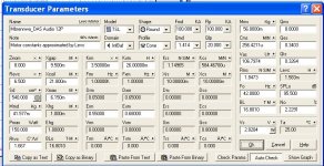
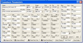
Leap uses 4 parameters Krm, Kxm, Erm, Exm to make a model of the impedance rise. It is used by some manufacturers also in their datasheets.
Briefly explained, two parameters represent inductance values and the other two the impedance slope, a set at a low and a high frequency.
In attach the description of it in the manual.
I have added also the transducer model of the DAS 12P as used by Leap.
Remark that Leap is an old package, I have the last 2007 version of it. It only runs in XP-mode. LinearX also has finished all its activities.
It has less sense to start with it today. I will also look for a replacement in the future, but it will be difficult to find, because it is very powerful and complete to make a total speaker design.
Attachments
Interesting, I will have a look at it. Maybe it can simulate waveguidesOne of the more promising alternatives to LEAP, seems to be VituixCAD.
") .
.It can simulate a large number of things, developer is active in a thread here on diyaudio. If you lack a specific function he may be glad to get some ideas on what to improve.
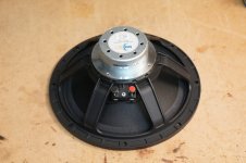
I received the Faital woofers (that's a breaktrhough new record for DPD, they delivered the parcel in their first attempt and only 1 day later than expected -- woohooo!).
They look nice and a quick impedance curve scan showed very nice consistency between the two drivers. Breaking in now...
Paul: do you have the math/formulas behind the LEAP "advance LTD" impedance model using all 12 parameters? The PDF does not say how exactly the LTD model works.
They look nice and a quick impedance curve scan showed very nice consistency between the two drivers. Breaking in now...
Paul: do you have the math/formulas behind the LEAP "advance LTD" impedance model using all 12 parameters? The PDF does not say how exactly the LTD model works.
Not exactly clear to me what you are looking for.
Do you want to calculate the TSP out of the measured impedance curve?
Or do you want to create an impedance curve by using some parameters, to obtain a curve that fits on the measured impedance in the best way, to obtain/check the TSP?
Remark that, all TSP can only be obtained by doing an extra measurement by adding some mass to the cone or by mounting the driver in a cabinet with known volume. Only in that way you obtain values for Mms and BL. You probably know that also.
For my own measurements, I check the absolute SPL at 1m/2.83Vrms with a good calibrated microphone and equipment to get all parameters. Or I use the Mms of the datasheet.
Not exactly clear to me what you are looking for.
Do you want to calculate the TSP out of the measured impedance curve?
Or do you want to create an impedance curve by using some parameters, to obtain a curve that fits on the measured impedance in the best way, to obtain/check the TSP?
I am looking for a model function that gives a good fit to measured impedance curves. The idea would be to implement this in the impedance model of MATAA. I am aware that this does not directly yield all TSP. But we're getting off topic here. Paul (and everyone), please get in touch with me via PM if you have the equations involved in the full LEAP impedance model (or other software packages).
Let's get back to the Monkey Coffin... the Faital woofers are warming up in the basement. I hope they will soon be ready for measurements.
Here's an update from the woofer tests.
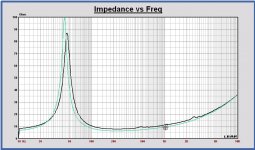
First of all, I made a small mistake with the measurements of the D.A.S. 12P impedance (the fixture blocked part of the venting hole of the magnet). Please ignore the D.A.S. 12P data from my post 218.
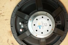
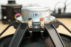
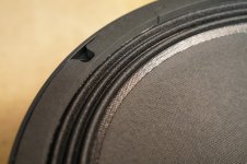
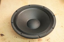
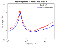
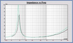
I attached the new measurements from the D.A.S. 12P and also from the FaitalPRO 12PR320, along with some photos of the Faital.
Paul: can you redo the TSPs for the D.A.S. and also for the Faital?
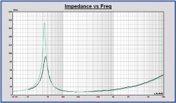
The impedance curves of the two woofers are very similar. In general, the D.A.S. has slightly higher impedance, and the impedance rise > 300 Hz is a bit stronger. The D.A.S. shows a few small impedance blips at about 350 Hz (and higher frequencies), which might hint to resonances (suspension, cone). The Faital also has some (fewer) blips starting at about 470 Hz, so it's clean throughout most of the intended pass band of < 500 Hz.
I am working on a setup to determine the non-linear distortion of the two woofers. However, that will have to wait until everyone is out of the house because the test is very loud and takes a while to complete.
First of all, I made a small mistake with the measurements of the D.A.S. 12P impedance (the fixture blocked part of the venting hole of the magnet). Please ignore the D.A.S. 12P data from my post 218.
I attached the new measurements from the D.A.S. 12P and also from the FaitalPRO 12PR320, along with some photos of the Faital.
Paul: can you redo the TSPs for the D.A.S. and also for the Faital?
The impedance curves of the two woofers are very similar. In general, the D.A.S. has slightly higher impedance, and the impedance rise > 300 Hz is a bit stronger. The D.A.S. shows a few small impedance blips at about 350 Hz (and higher frequencies), which might hint to resonances (suspension, cone). The Faital also has some (fewer) blips starting at about 470 Hz, so it's clean throughout most of the intended pass band of < 500 Hz.
I am working on a setup to determine the non-linear distortion of the two woofers. However, that will have to wait until everyone is out of the house because the test is very loud and takes a while to complete.
Attachments
-
 DSC08556.resized.JPG758.7 KB · Views: 186
 -
 DSC08555.resized.JPG700.4 KB · Views: 180
 -
 DSC08554.resized.JPG739.3 KB · Views: 344
 -
 DSC08553.resized.JPG789.4 KB · Views: 346
 -
 DSC08550.resized.JPG818 KB · Views: 355
 -
 woofers_impedance.png37.3 KB · Views: 368
 -
FaitalPRO_12PR320_impedance.frd.txt7 KB · Views: 47
-
DAS_12P_impedance.frd.txt7.1 KB · Views: 39
Last edited:
It looks like there is something wrong with your last measurements.
There is an impedance offset now w.r.t. the Leap model of the datasheet. In the measurement of post 218, there was a perfect match for low and high frequencies.
Do you know how accurate your measurements are?
For my own measurements it is better than 0.1E. I have calibrated my equipment with a reference resistor. For the TSP it is important to have a high accuracy.
Have you also measured the Re value? Best to do that separately.
Attachments
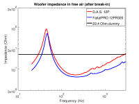
Hi Paul -- I was going to say that the measurement can't be wrong because I have not changed anything to my setup except the fixture for the woofer. To convince everyone I measured a 22.4 Ohm dummy resistor and sure enough, it was off. I found that I mixed up the low-frequency limit and the value of the reference resistor when I typed in those values, so the software thought the reference resistor is 10 Ohm instead of 8.1 Ohm. Aaargh!!!
So here are the measurements again. I also plotted the measurement of the 22.4 Ohm resistor (black line), which now shows up at 22.45 Ohm.
Can you please have another look?
Oh, I forgot to R-DC values. I measured them as 6.1 Ohm (DAS) and 5.7 Ohm (Faital).
So here are the measurements again. I also plotted the measurement of the 22.4 Ohm resistor (black line), which now shows up at 22.45 Ohm.
Can you please have another look?
Oh, I forgot to R-DC values. I measured them as 6.1 Ohm (DAS) and 5.7 Ohm (Faital).
Attachments
Hi Matthias,
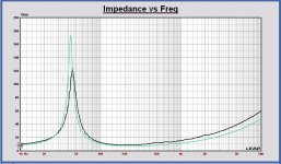
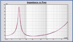
Now it is more than ok.
In all plots:
- your measurement in black
- Leap model based on datasheet in green
- Leap model based on your measurement for best fit in red.
For the DAS 12P Leap model based on the measurement:
- Re: 6.5 --> 6.1 Ohm
- fs: 42.0 --> 44.4 Hz
- Qms: 10.3 --> 5.7
- BL: 16.8 --> 16.0 N/A
By only changing Re, fs and Qms, the fit is not perfect, see plot. Also possible that Mms is different and not the BL, but BL is expected more to be different. Only with the impedance curve this is not possible, like mentioned before.
For the Faital 12PR320 Leap model based on the measurement:
- Re: 5.3 --> 5.7 Ohm
- fs: 42.0 --> 46.0 Hz
- Qms: 7.8 --> 6.2
- BL: 13.5 --> 13.0 N/A
Same remark about BL or Mms change.
I had the following experience in the past. Using a swept sine for an impedance measurement, the sweep rate can have impact on the measurement, because of dynamic tracking errors. I had that problem with the Clio, using a too fast sweep rate with a lower Zmax and a different clock shape as a consequence.
But probably you are aware of this.
Attachments
-
 Faital 12PR320 Leap model.JPG97.4 KB · Views: 78
 -
 Faital 12PR320 Imp meas vs. Leap model measurement BL=13.5 Qms=5.8.JPG118.2 KB · Views: 67
 -
 Faital 12PR320 Imp meas vs. Leap model measurement BL=13.0 Qms=6.2.JPG117 KB · Views: 69
 -
 Faital 12PR320 Imp meas vs. Leap model datasheet.JPG114.8 KB · Views: 749
 -
 DAS 12P Leap model.JPG100.8 KB · Views: 764
 -
 DAS 12P Imp meas vs. Leap model measurement BL=16.8 Qms=5.2 .JPG117.2 KB · Views: 755
 -
 DAS 12P Imp meas vs. Leap model measurement BL=16.0 Qms=5.7 .JPG110.2 KB · Views: 759
 -
 DAS 12P Imp meas vs. Leap model datasheet.JPG116.3 KB · Views: 777
Using a swept sine for an impedance measurement, the sweep rate can have impact on the measurement, because of dynamic tracking errors. I had that problem with the Clio, using a too fast sweep rate with a lower Zmax and a different clock shape as a consequence.
But probably you are aware of this.
Hmm, I could guess about what you mean by "dynamic tracking errors", but I am not quite sure. Can you explain this a bit more?
Distortion tests are beeping away in the basement...
Last edited:
Hmm, I could guess about what you mean by "dynamic tracking errors", but I am not quite sure. Can you explain this a bit more?
Distortion tests are beeping away in the basement...
Maybe tracking error is not the correct name, but impedance and frequency value have to be read/sampled at the same time. I see this problem with the Clio for high frequency sweep rates. I compared it with a dynamic tracking error in a PLL for example, where the output is not following the input, if the input is a slope and the PLL bandwidth is limited. In this case reading the impedance value is not following frequency value
. I understand the Clio problem in that way.Edit: Or there is some tracking error caused by the driver for higher input frequency sweep rates... then it has to be calculated...not now.
Last edited:
Distortion tests are beeping away in the basement...
Have you checked the resonance frequency of the basement before?
...
Distortion tests are beeping away in the basement...
Ah, the first beeps of what is to become "The MonkeyBox™"
I am eagerly anticipating each and every post here.
Have you checked the resonance frequency of the basement before?
Beeps are done, house is still intact (seems I did not hit its resonance
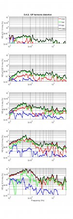
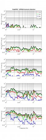
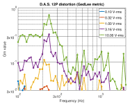
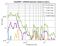
).I attached some figures showing non-linear distortion from the D.A.S. 12P and the FaitalPRO 12PR320 (harmonic distortion, GedLee) as a function of drive level and frequency. For these measurements I placed the microphone tip 15 cm away from the "front/gasket plane" of the driver. My ISEMCON EMX-7150 microphone is specified at a about < 0.03% THD at the SPL levels involved here. I used discrete sine test signals (not the Farina sweep method).
Note that comparison of these distortion measurements with measurements from elsewhere may not be straightforward. In my experience, the measurement setup, equipment and signal processing may have a substantial effect on the overall distortion and noise levels.
I think the GedLee stuff is an interesting approach to put the "shape" of the non-linearities into perspective. See here and here (or take a look at the original papers 1 and 2).
Overall, the Faital has somewhat lower distortion, which is dominated by 2nd order harmonic. With the D.A.S., 3rd order starts to become dominant above 1 Vrms drive.
Attachments
Looking at the past few posts provide some insights that might help choosing the best woofer. Impedance curves and distortion measurements show that both might work out for the Monkey Coffin in some way, but maybe one is better than the other.
Impedance curves show that the D.A.S. 12P has a much lower Qms than specified in the datasheet (Qms = 5, not 10). The high Qms was my main reason why I wanted to take a closer look at the D.A.S. Also, it looks like the D.A.S. response is not as clean as the Faital response in the intended pass band (up to about 500 Hz), as shown by the distortion measurements and some (minor) blips in the impedance response. Based on this I'd favor the Faital, but...
The Faital 12PR320 impedance curve seems to indicate a slightly weaker motor than specified in the datasheet, as Qes is a bit higher than specified (taken from Pauls LEAP screenshots): Qes = 0.50 (not 0.39 as in the datasheet), Qts = 0.46 (not 0.37). Will those different values still work out well for the box tuning and the SPL requirements of the Monkey Coffin?
Just some thoughts about the impedance measurements to be sure the measurement is correct:
- voltage level on the terminals: my own experience is, that a voltage of minimum 1Vrms is required for the most representative TSP values for the application. At lower levels the TSP become different. In most cases fs becomes higher and Qms lower, probably due to suspension non-linearity's. It is strongly dependent on the driver type.
- impedance fitting: now only changed BL and not Mms. The Q-factor will remain the same, but the SPL calculated with TSP will be different.
- sine sweep rate to be checked, if there is no impact on the impedance shape, already mentioned
The Q-factor of the Faital is a lot different. We have to look to its BR alignment, a little SPL boost can be expected. Therefore my remark about the voltage measurement level if the Q is measured correctly.
Just some thoughts about the impedance measurements to be sure the measurement is correct:
- voltage level on the terminals: my own experience is, that a voltage of minimum 1Vrms is required for the most representative TSP values for the application. At lower levels the TSP become different. In most cases fs becomes higher and Qms lower, probably due to suspension non-linearity's. It is strongly dependent on the driver type.
- impedance fitting: now only changed BL and not Mms. The Q-factor will remain the same, but the SPL calculated with TSP will be different.
- sine sweep rate to be checked, if there is no impact on the impedance shape, already mentioned
The test voltage in my measurements was 0.707 V-RMS. I have checked with different voltages (factor 10 higher and lower), and that made absolutely no difference. I have also checked different sweep rates, and that made no difference, too.
The Q-factor of the Faital is a lot different. We have to look to its BR alignment, a little SPL boost can be expected. Therefore my remark about the voltage measurement level if the Q is measured correctly.
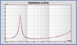
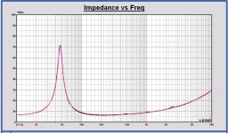
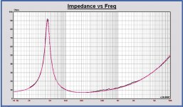
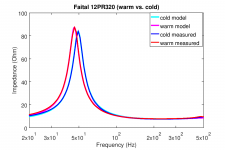
Thinking about this a bit more I realised that the drivers were sitting in a warm room (heating next to my workshop) before I made the measurements. As temperature has an effect on magnetic strength and compliance of the suspension parts, I repeated the measurements after the drivers were sitting in my workshop for a while (no heating, and winter is coming...). The different curves are attached.
Just for the heck of it I implemented the Wright impedance model to MATAA (as far as I can tell, that's the same model you used in LEAP). Using that model, I got the following Qes, Qms and f0 values from the impedance model curves (cyan and magenta curves in the attachment):
Warm:
Qms = 5.7
Qes = 0.43
Qts = 0.40
f0 = 46 Hz
Cold:
Qms = 5.7
Qes = 0.45
Qts = 0.42
f0 = 49.4 Hz
The warm/cold difference is not huge, so nothing to worry about. However, my Qes values are lower than those shown in your LEAP screenshots, and they are closer to the datasheet values. If my numbers are right, I'd say the Faital parameters given in the datasheet are ok. Any ideas why the LEAP numbers are higher?
Attachments
- Home
- Loudspeakers
- Multi-Way
- Open Source Monkey Box