Hey everybody,
I'm wanting to rework one of the first pairs of speakers I built with some better design. The drivers are going to be Goldwood GW-8028 8":
Goldwood GW-8028 8" Butyl Surround Woofer 8 Ohm
And GT-510 1" Soft Dome Tweet:
Goldwood GT-510 1" Soft Dome Tweeter
I designed this crossover with the advice and formulas provided in the intro to designing without measuring thread, but I'd like to get sort of a sanity check and second (or third or fourth etc) opinion before moving forward.
Here's the diagram I came up with:

(substitute the second R1 that's clearly an inductor with I1, I had a derp moment)
BOM:
R1: 4.3R
R2: 10R
R3: 9.1R
C1: 4.3uF
C2: 6.8uF
I1: .35mH
I2: .60mH
Here's some notes on this: values are rounded to the nearest value that's available on PE. One thing I'm really not sure about is the HP filter, as I had to round both the inductor and the capacitor up, and I don't know if the resonance between them will behave as expected. Another thing I wasn't sure about was the type of cap for C2. My thought is that an electrolytic should be okay, since it's not directly in the signal path, and the electros are significantly cheaper than the film caps at that value.
You may notice that the -6dB points for the woofer and the tweeter don't match up, but that's on purpose as the woofer has a sharp +6dB breakup peak that should coincide with the -6 point on the xover, but that's one of the things I was wanting advice on.
I was also wondering about BSC. If I wanted the attenuation to be for both the woofer and the tweeter, could I place the filter before the crossover board and have it apply to both, or will that significantly compromise HF performance? My biggest concern on that is that the woofer is fairly low efficiency and I'm having to add quite a lot of attenuation to the tweeter to bring it down. I don't want to add too much resistance in front of the tweeter, as that just becomes wasted heat and lowers overall system efficiency.
I think that's all the questions I had, but if I remember anything else I'll be sure to post it. Thanks in advance!
I'm wanting to rework one of the first pairs of speakers I built with some better design. The drivers are going to be Goldwood GW-8028 8":
Goldwood GW-8028 8" Butyl Surround Woofer 8 Ohm
And GT-510 1" Soft Dome Tweet:
Goldwood GT-510 1" Soft Dome Tweeter
I designed this crossover with the advice and formulas provided in the intro to designing without measuring thread, but I'd like to get sort of a sanity check and second (or third or fourth etc) opinion before moving forward.
Here's the diagram I came up with:
(substitute the second R1 that's clearly an inductor with I1, I had a derp moment)
BOM:
R1: 4.3R
R2: 10R
R3: 9.1R
C1: 4.3uF
C2: 6.8uF
I1: .35mH
I2: .60mH
Here's some notes on this: values are rounded to the nearest value that's available on PE. One thing I'm really not sure about is the HP filter, as I had to round both the inductor and the capacitor up, and I don't know if the resonance between them will behave as expected. Another thing I wasn't sure about was the type of cap for C2. My thought is that an electrolytic should be okay, since it's not directly in the signal path, and the electros are significantly cheaper than the film caps at that value.
You may notice that the -6dB points for the woofer and the tweeter don't match up, but that's on purpose as the woofer has a sharp +6dB breakup peak that should coincide with the -6 point on the xover, but that's one of the things I was wanting advice on.
I was also wondering about BSC. If I wanted the attenuation to be for both the woofer and the tweeter, could I place the filter before the crossover board and have it apply to both, or will that significantly compromise HF performance? My biggest concern on that is that the woofer is fairly low efficiency and I'm having to add quite a lot of attenuation to the tweeter to bring it down. I don't want to add too much resistance in front of the tweeter, as that just becomes wasted heat and lowers overall system efficiency.
I think that's all the questions I had, but if I remember anything else I'll be sure to post it. Thanks in advance!
Hi,
What you currently have designed isn't very listenable ( IMHO ).
- There's too much overlap between the two sections and the tweeter level is much too hot ( for most people's taste I reckon ).
- OTOH, the impedance curve looks nice.
Here are the .frd + .zma files for both of those drivers ( > created by using the SPL Trace tool within VituixCAD2 ).
You'll be doing yourself a favor if you take these files and eventually plug them into one of the many free Crossover simulators ( assuming that in the future you might want to learn how to design an effective network ).
Perhaps you should take this all up ( off-line ) with the author of the thread that you referenced.
I figure both could benefit from a comparison of notes to figure out where you went wrong ( something went amiss, for whatever reason ).
I suspect the directions within that thread need some tweaking so that better outcomes can be achieved ( since it is an official sticky ).
")
What you currently have designed isn't very listenable ( IMHO ).
- There's too much overlap between the two sections and the tweeter level is much too hot ( for most people's taste I reckon ).
- OTOH, the impedance curve looks nice.
Here are the .frd + .zma files for both of those drivers ( > created by using the SPL Trace tool within VituixCAD2 ).
You'll be doing yourself a favor if you take these files and eventually plug them into one of the many free Crossover simulators ( assuming that in the future you might want to learn how to design an effective network ).
Perhaps you should take this all up ( off-line ) with the author of the thread that you referenced.
I figure both could benefit from a comparison of notes to figure out where you went wrong ( something went amiss, for whatever reason ).
I suspect the directions within that thread need some tweaking so that better outcomes can be achieved ( since it is an official sticky ).
Attachments
Thanks Earl, one of the reasons I brought it here at this stage was the lack of FRD and ZMA files from the manufacturer, I do actually have XSim, just didn't have anything to plug into it for these. I think one of the reasons for the overlap is it wasn't clear to me if the "crossover point" for those calculations was the -3 point or the -6 point. With the data files, though, I'll be able to at least approximate through simulation, and then bring back the results here. Might be a couple of days, though, as I only have XSim on my desktop and it's packed away right now from moving house.
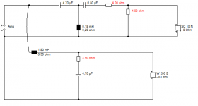
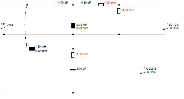
I can see where this circuit is coming from, with a bit of impedance correction after the small bass coil. But, IMO, the bass balance will be way too light.
The tweeter is quite loud, and has a large Fs resonance around a whopping 28 ohms, so it needs some resistive shunt. An attenuator will do.
I'd play with this circuit's red values in your sim. 3kHz negative polarity crossover. Should sound OK. Been done before, you see. There really aren't any good second order filters for 8" bass because of the bad time alignment, and first order would be silly unless you like destroying tweeters.
Attachments
Well, Dave, I won't disagree that the drivers aren't good, but that also depends on your expectations and goals. If you're trying to do critical listening on well recorded material, of course they're going to fall short. But if you're trying to make a decent sounding pair of party speakers that go deep and get loud... They do just fine. But, like I said, I already have the drivers, just trying to get the most out of them. And I think these goldwoods are the cheapest 8" on PE without stepping down to GRS.
system7, thanks for putting that together for me. When I get my desktop up and running again I'll see how it looks using the files provided by Earl. I'll probably try the one I designed, too, just to see how they compare and post results here.
system7, thanks for putting that together for me. When I get my desktop up and running again I'll see how it looks using the files provided by Earl. I'll probably try the one I designed, too, just to see how they compare and post results here.
Eventually this woofer may end up being relegated to WAW duty with a FaitalPro fullrange driver, but right now it'll be paired with a tweeter. Pretty much anything will be better than what they're doing now, which is running wide open with a Pyle 98 dB bullet tweeter handling the HF content using just the included mylar cap. Like I said, I built these before I had any real idea what I was doing, and only got lucky with the cabinet dimensions working out.
Eventually this woofer may end up being relegated to WAW duty with a FaitalPro fullrange driver
2.5 mm Xmax ?! Not that much for a woofer
I thought that polycone bass driver had a quite reasonable frequency response. It's really a car parcel shelf woofer with a high Qts around 0.8.
I hadn't noticed the high Qts initially, but that means it tends to a bass lump at the bottom end in small boxes. I might reconsider the bafflestep coil to account for that:
1mH and 9.1 ohms and 6.8uF might be a good place to start after all. Maybe 30-60L closed box. It will never be flat, but might be OK.
The tweeter circuit won't be affected except on level.
Hey Guys,
Got my desktop up and running and was able to get this simmed. I played with the values of a few things but mostly just used the numbers system7 gave, most notably changing R1 and R2 to get the tweeter level a little lower. Of course, no phase data so I don't know how it's REALLY going to behave around the crossover frequency, but it looks a lot better than what I imagine it looks like right now.


Got my desktop up and running and was able to get this simmed. I played with the values of a few things but mostly just used the numbers system7 gave, most notably changing R1 and R2 to get the tweeter level a little lower. Of course, no phase data so I don't know how it's REALLY going to behave around the crossover frequency, but it looks a lot better than what I imagine it looks like right now.
Interesting mis-interpretation of Steves comments on BSC.
You've added a 1668hz notch filter ( L3,C4,R4 ) that seems to have had a positive outcome.
I understand what you're saying now. Didn't do exactly that, but I did play around with a lot of different things and got what looks to be a much better frequency response graph. Bonus: the tweeter now never drops below 8R. That dip around 700 Hz is also much less pronounced now. One bad thing is that system sensitivity is down to around 81 dB, yikes! But then again, that's what you get for starting with an 84 dB driver for your bass... What do you guys think, where do I need to go next?


What is your thinking behind your choosing to you locate L3 & R4 in the above location?
Your best next step is to actually buy some passive components / wire up one of your designs and then see how it sits with your ears.
It's likely you'll find the tweeter is not as efficient as is claimed by GoldWood / meaning you'll need to redesign ( whatever ) network to the discovered "new-reality".
Once you realize that there's no substitute to using files ( from your own measurements ) you'll need to get a measurement package.
- Status
- This old topic is closed. If you want to reopen this topic, contact a moderator using the "Report Post" button.
- Home
- Loudspeakers
- Multi-Way
- Crossover Design Help