Hi David
I still think it would be extremely difficult to get a consistent profile trying to blind fill a 2.5m tube of 2.5cm dia. I'm still not convinced it would help me.
I agree, there is no need for the SWR and it is still a PWT.
I don't know the details of how REW processes samples and I don't know what the error term is. I'll think about it some more because, I don't know.") Do you have an experiment in mind to prove/disprove this? or alternate measurement s/w ?
Do you have an experiment in mind to prove/disprove this? or alternate measurement s/w ?
I still think it would be extremely difficult to get a consistent profile trying to blind fill a 2.5m tube of 2.5cm dia. I'm still not convinced it would help me.
I agree, there is no need for the SWR and it is still a PWT.
I don't know the details of how REW processes samples and I don't know what the error term is. I'll think about it some more because, I don't know.
Do you have an experiment in mind to prove/disprove this? or alternate measurement s/w ?
Last edited:
Acoustic impedance tube
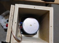
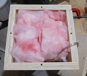
Another piece of test gear I've wanted is for measuring material sound absorption coefficients (damping). It's based on ASTM E1050-10 or ISO 10534-2 and there are a few published projects to create one without needing to buy the official publications. I'm hoping it will be sufficient using these simple materials and better than guessing. End goal is for BEM models.
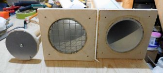
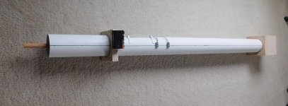
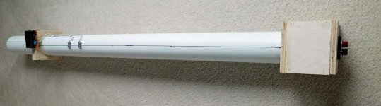
This one is based on a 75mm dia x 1m long tube with a 20cm sample chamber. These impedance tubes typically use 2 mics placed in 2 of 3 positions for 2 freq ranges. I currently only have one set of mic positions for the [300Hz->2500Hz] range but another mic hole will provide [80Hz->700Hz] .
The two electret mic modules are from a previous project. The local preamp gain and filters have been modified to extend the bandwidth. They run on batteries to reduce noise and prevent ground loops. The max output is ~1Vrms (line level) intended to be connected to the stereo LineIn of a sound card. A PC83-8 full range driver is a perfect fit for the 75mm tube. The total cost is ~$50 CDN if you had to buy all the parts.
At this point the sample chamber plunger still requires a seal and there is some programming (scripting) required in Octave to process the data.
These are some good free docs that describe impedance tubes at:
https://pdfs.semanticscholar.org/5409/4a8f000ebe448fc3d2913075834a47b94d4e.pdf
http://web.engr.uky.edu/~dherrin/Bandung/10_Impedance_Tube.pdf
.
Another piece of test gear I've wanted is for measuring material sound absorption coefficients (damping). It's based on ASTM E1050-10 or ISO 10534-2 and there are a few published projects to create one without needing to buy the official publications. I'm hoping it will be sufficient using these simple materials and better than guessing. End goal is for BEM models.
This one is based on a 75mm dia x 1m long tube with a 20cm sample chamber. These impedance tubes typically use 2 mics placed in 2 of 3 positions for 2 freq ranges. I currently only have one set of mic positions for the [300Hz->2500Hz] range but another mic hole will provide [80Hz->700Hz] .
The two electret mic modules are from a previous project. The local preamp gain and filters have been modified to extend the bandwidth. They run on batteries to reduce noise and prevent ground loops. The max output is ~1Vrms (line level) intended to be connected to the stereo LineIn of a sound card. A PC83-8 full range driver is a perfect fit for the 75mm tube. The total cost is ~$50 CDN if you had to buy all the parts.
At this point the sample chamber plunger still requires a seal and there is some programming (scripting) required in Octave to process the data.
These are some good free docs that describe impedance tubes at:
https://pdfs.semanticscholar.org/5409/4a8f000ebe448fc3d2913075834a47b94d4e.pdf
http://web.engr.uky.edu/~dherrin/Bandung/10_Impedance_Tube.pdf
.
Attachments
Hi Don
I do plan to use a clear acrylic or polycarbonate tube so I won't have to do it literally blind.
I think we are not "blind" because the impulse response will tell how the absorption behaves, Time Domain Reflectometry with acoustic waves!
I am not sure how consistent the profile needs to be - provided we absorb the back wave then the profile details should make little difference.
Or that's my assumption behind why I think (hope?) it shouldn't be too difficult.
But yes, easy to propose when I haven't actually done it yet.
I don't know the details of REW either, luckily the author answers questions on-line so we have that option.
I believe the sample time/resolution trade-off is classic theory but it's not clear to me that it's impossible to do better - so I will try to think of an experiment.
Thank you for this reply, it has made me think too!
Best wishes
David
I still think it would be extremely difficult...to blind fill a 2.5m tube of 2.5cm dia.
I do plan to use a clear acrylic or polycarbonate tube so I won't have to do it literally blind.
I think we are not "blind" because the impulse response will tell how the absorption behaves, Time Domain Reflectometry with acoustic waves!
I am not sure how consistent the profile needs to be - provided we absorb the back wave then the profile details should make little difference.
Or that's my assumption behind why I think (hope?) it shouldn't be too difficult.
But yes, easy to propose when I haven't actually done it yet.
I don't know the details of how REW processes samples and I don't know what the error term is. I'll think about it some more because, I don't know.
I don't know the details of REW either, luckily the author answers questions on-line so we have that option.
I believe the sample time/resolution trade-off is classic theory but it's not clear to me that it's impossible to do better - so I will try to think of an experiment.
Thank you for this reply, it has made me think too!
Best wishes
David
Another piece of test gear I've wanted is for measuring material sound absorption coefficients (damping).
Data from this test will be quite informative, and quite useful. A lot of the absorption data on fiberglass, mineral wool, etc., was taken a long time ago, and the exact test methodology is unclear. It would be nice to have a consistent set of data for all the common MODERN materials we use today... at varying densities.
As always, I find your postings to be very valuable.
j.
Acoustic impedance tube - processing the data
The scripts that generate the test signal and process the mic data are nearly finished
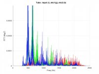
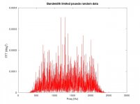
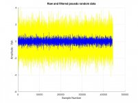
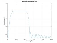
Pics [1,2,3] : I'm using the transfer function method, so I need a pseudo random test signal but it also needs to be bandwidth limited because the current tube and mic positions are suitable for 300-2500Hz. I used a digital FIR 255tap that attenuates ~ -20dB at the tubes corner freqs. Pics below show the filter (pic1), the random signal before/after (pic2)and the bandwidth limited FFT spectrum (pic3). I can capture sufficient data in just a 1 sec burst.
The transfer function and reflection factor is calculated based on the published paper formulas using the mic data's complex FFT, physical spacing distances and complex attenuation factor. I used the complex attenuation factor because the tube length exceeds 3x diameter and its claimed to be more accurate.
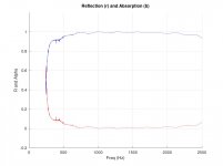
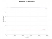
Pics [4,5] : I also made a "virtual" tube, in Octave, to test the processing scripts. This allows some ideal test cases, like no reflections (pic#4), and LP digital 2nd order IIR attenuation of reflections to test frequency dependencies (pic#5).
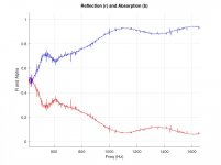
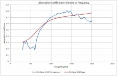
Pics [6,7] : The first attempt with the physical tube was just to verify the drive (via headphone) and microphone preamp levels (via Line in). I packed 10cm of poly in the sample chamber and took a few measurements to verify that I had enough dynamic range. I still need to calibrate the mic differences, and add a seal to the plunger (tube leaks), and add frequency averaging to smooth things. However, for a test flight, it appears to be working. There is a frequency dependent standing wave in the tube (pic6, FFT), and the attenuation increases with freq (pic7). Real measurements will also include the sample's mass and volume to get its density to produce material curve sets (absorption vs density vs frequency).
If there is interest, I can spin out this topic to a new thread and publish some data for damping materials.
.
The scripts that generate the test signal and process the mic data are nearly finished
Pics [1,2,3] : I'm using the transfer function method, so I need a pseudo random test signal but it also needs to be bandwidth limited because the current tube and mic positions are suitable for 300-2500Hz. I used a digital FIR 255tap that attenuates ~ -20dB at the tubes corner freqs. Pics below show the filter (pic1), the random signal before/after (pic2)and the bandwidth limited FFT spectrum (pic3). I can capture sufficient data in just a 1 sec burst.
The transfer function and reflection factor is calculated based on the published paper formulas using the mic data's complex FFT, physical spacing distances and complex attenuation factor. I used the complex attenuation factor because the tube length exceeds 3x diameter and its claimed to be more accurate.
Pics [4,5] : I also made a "virtual" tube, in Octave, to test the processing scripts. This allows some ideal test cases, like no reflections (pic#4), and LP digital 2nd order IIR attenuation of reflections to test frequency dependencies (pic#5).
Pics [6,7] : The first attempt with the physical tube was just to verify the drive (via headphone) and microphone preamp levels (via Line in). I packed 10cm of poly in the sample chamber and took a few measurements to verify that I had enough dynamic range. I still need to calibrate the mic differences, and add a seal to the plunger (tube leaks), and add frequency averaging to smooth things. However, for a test flight, it appears to be working. There is a frequency dependent standing wave in the tube (pic6, FFT), and the attenuation increases with freq (pic7). Real measurements will also include the sample's mass and volume to get its density to produce material curve sets (absorption vs density vs frequency).
If there is interest, I can spin out this topic to a new thread and publish some data for damping materials.
.
Attachments
Good progress I'm sure the data would be valuable, maybe an ABEC cardioid optimization will become more practical soonIf there is interest, I can spin out this topic to a new thread and publish some data for damping materials.
acoustic impedance tube - test samples
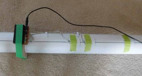
The tube was modified with a seal for the sample plunger, another port added for a 3rd mic position, and a brake for the sample plunger. Most of the damping material is "springy" if compressed, and the brake holds the plunger position (volume). The 3rd mic port is to support 2 freq ranges and provides a 3rd port to relieve static pressure when the plunger is moved. Pics#1,2. The s/w also had some frequency averaging and some smoothing added.
The tube range (on high) should theoretically be [300,2500] however I have noticed measurements are clean from [340,2300] which may be related to the mic size or their acoustic centers. Not a problem for me.
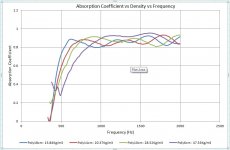
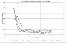
First material test run was with 13g (measured using a postal scale) of polyester fill, and varied sample volume to change the density. Pic#3 has the reflection curves and Pic#4 has the absorption curves for various densities. The curves only show magnitude but the coefficients are complex and carry phase information as well. Sufficient for modelling.
A sample of acoustic tile (USG-Radar-2120) was also measured, because it had some published data (but only 4 data points) and had fixed volume (thickness). Acoustic tiles are measured using a different ASTM spec , but the absorption figures should be "ballpark" correct in the impedance tube.
The tube was modified with a seal for the sample plunger, another port added for a 3rd mic position, and a brake for the sample plunger. Most of the damping material is "springy" if compressed, and the brake holds the plunger position (volume). The 3rd mic port is to support 2 freq ranges and provides a 3rd port to relieve static pressure when the plunger is moved. Pics#1,2. The s/w also had some frequency averaging and some smoothing added.
The tube range (on high) should theoretically be [300,2500] however I have noticed measurements are clean from [340,2300] which may be related to the mic size or their acoustic centers. Not a problem for me.
First material test run was with 13g (measured using a postal scale) of polyester fill, and varied sample volume to change the density. Pic#3 has the reflection curves and Pic#4 has the absorption curves for various densities. The curves only show magnitude but the coefficients are complex and carry phase information as well. Sufficient for modelling.
A sample of acoustic tile (USG-Radar-2120) was also measured, because it had some published data (but only 4 data points) and had fixed volume (thickness). Acoustic tiles are measured using a different ASTM spec , but the absorption figures should be "ballpark" correct in the impedance tube.
Attachments
Closed box, damping
Damping is usually added after the build, in some experimentally determined amount, to fix reflections or standing waves in the closed box.
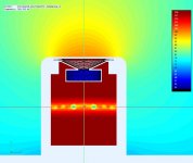
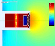
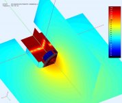
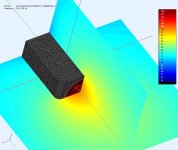
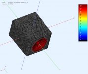
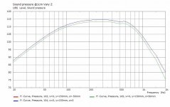
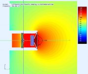
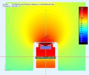
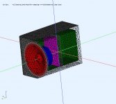
I created an ABEC model of a single woofer chamber used in my quad woofer tower. This is an easy way to see what is happening in the rear chamber. There is a clear standing wave @718Hz in the rear chamber as shown in the simulations. I would like to add damping material in the simulations to determine the optimal amount and placement. I can check the sim model against the actual unit.
The pressure in the box in significantly higher than outside (expected) and the standing wave causes a dip in FR. The rear chamber is net ~6L and 24cm deep. The SPL measurement is from the simulation taken close to the woofer cone to exclude any baffle step effects.
Damping is usually added after the build, in some experimentally determined amount, to fix reflections or standing waves in the closed box.
I created an ABEC model of a single woofer chamber used in my quad woofer tower. This is an easy way to see what is happening in the rear chamber. There is a clear standing wave @718Hz in the rear chamber as shown in the simulations. I would like to add damping material in the simulations to determine the optimal amount and placement. I can check the sim model against the actual unit.
The pressure in the box in significantly higher than outside (expected) and the standing wave causes a dip in FR. The rear chamber is net ~6L and 24cm deep. The SPL measurement is from the simulation taken close to the woofer cone to exclude any baffle step effects.
Attachments
Damping considerations
I was looking for rationales for how to determine how much and where to place the damping material. I currently have fibreglass nominally 12cm slightly compressed to 8cm at the rear wall and it seems to work. That being said I don't know if it's the best amount or in the best location.
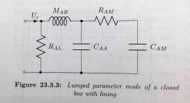
Pic#1 : is a lumped circuit equivalent of a closed box with damping taken from Kolbrek's Horn book. It's suppose to be valid for box dimensions up to wavelength/2. The box tuning (Q) was based on the volume of open rear chamber air (Caa equivalent). As I add damping material, "Caa" decreases, while "Ram" and "Cam" increase, causing losses and Q to decrease (like a larger box). I would like to maintain the original box design Q.
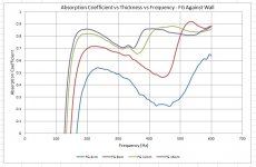
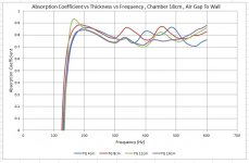
Pic#2, #3 : Since I require effective damping at a min 718Hz (first dip), I used Fiberglass because it was easy to get and effective at lower freq. I loaded the impedance tube with nominal thickness [4cm, 8cm, 12cm,16cm] samples using the tube's low range (80-600Hz). Pic#2 is for the samples backed against a solid wall, Pic#3 is for samples with an air gap between the sample and the wall. The results are as expected, since damping is dependent on particle velocity, and there is a velocity gradient that approaches zero velocity at the wall, you could use less by material by centering it.
.
I was looking for rationales for how to determine how much and where to place the damping material. I currently have fibreglass nominally 12cm slightly compressed to 8cm at the rear wall and it seems to work. That being said I don't know if it's the best amount or in the best location.
Pic#1 : is a lumped circuit equivalent of a closed box with damping taken from Kolbrek's Horn book. It's suppose to be valid for box dimensions up to wavelength/2. The box tuning (Q) was based on the volume of open rear chamber air (Caa equivalent). As I add damping material, "Caa" decreases, while "Ram" and "Cam" increase, causing losses and Q to decrease (like a larger box). I would like to maintain the original box design Q.
Pic#2, #3 : Since I require effective damping at a min 718Hz (first dip), I used Fiberglass because it was easy to get and effective at lower freq. I loaded the impedance tube with nominal thickness [4cm, 8cm, 12cm,16cm] samples using the tube's low range (80-600Hz). Pic#2 is for the samples backed against a solid wall, Pic#3 is for samples with an air gap between the sample and the wall. The results are as expected, since damping is dependent on particle velocity, and there is a velocity gradient that approaches zero velocity at the wall, you could use less by material by centering it.
.
Attachments
IHR
Hi Don,
if you have a distinct peak you could use an internal Helmholtz resonator like discussed here:
Helmholtz Resonator Inside a Sealed Cabinet
Hi Don,
if you have a distinct peak you could use an internal Helmholtz resonator like discussed here:
Helmholtz Resonator Inside a Sealed Cabinet
In hindsight, it seems that I have totally messed in my original damping scheme for the woofer chambers. I have 12cm FG compressed to 8cm at the back wall behind my wall braces. Neither condition is optimal, so I opened up both towers and changed it to 8cm FG roughly in the middle. It does loosely touch the back in order to keep the FG in the middle.
A few pics from the simulation showing the pressures, and the last one from actual measurements before / after damping.
Even though the walls are short and braced I suspect they still vibrate. It would be interesting to use an accelerometer to determine the transfer function between the driver and walls. Then apply CLD to see it it can be improved / reduced. A suitable accelerometer (DR=+/-100G, BW=20Khz) would cost ~$100. Maybe later
.
Attachments
D2200Ph 2inch midrange driver
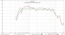
Moving back to the horn system, where another item I think can be improved is the midrange horn performance. I bought 1 inch throat horns advertised to work to 400Hz and 500Hz but in reality they are shortish horns able to operate reasonably to 800Hz and 1000Hz. I can EQ a flattish FR @725Hz but I would like to cross a little lower with less effort.
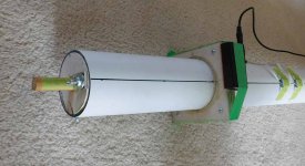
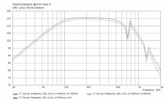
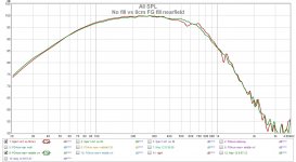
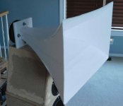
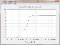
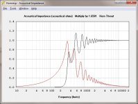
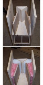
So I bought a pair of budget 2inch budget drivers that advertise operation to 500Hz using a particular horn that I don't have. Hornresp is able to generate classic horn curves and export the profile as CSV . This is enough to create an acoustic test load using a 300Hz exponential horn (in foamboard) with predictable cutoff and loading. The horn is 40cm axial with rectangular mouth 51cm x 31cm (big ).
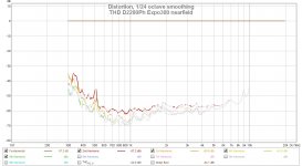
Some EQ was applied to make the FR flattish. Measurements were made using a direct connection to a Tripath amp (no caps or filters). Enough info to confirm this driver can operate with sufficient range for me with a little EQ.
.
Moving back to the horn system, where another item I think can be improved is the midrange horn performance. I bought 1 inch throat horns advertised to work to 400Hz and 500Hz but in reality they are shortish horns able to operate reasonably to 800Hz and 1000Hz. I can EQ a flattish FR @725Hz but I would like to cross a little lower with less effort.
So I bought a pair of budget 2inch budget drivers that advertise operation to 500Hz using a particular horn that I don't have. Hornresp is able to generate classic horn curves and export the profile as CSV . This is enough to create an acoustic test load using a 300Hz exponential horn (in foamboard) with predictable cutoff and loading. The horn is 40cm axial with rectangular mouth 51cm x 31cm (big
). Some EQ was applied to make the FR flattish. Measurements were made using a direct connection to a Tripath amp (no caps or filters). Enough info to confirm this driver can operate with sufficient range for me with a little EQ.
.
Attachments
Hi Don,
if you have a distinct peak you could use an internal Helmholtz resonator like discussed here:
Helmholtz Resonator Inside a Sealed Cabinet
or a sealed transmission line or inverted pyramid shaped internal enclose. or not?
edit: found this picture. i do not know where i got it from so i hope its okay to share it
edit2: nevermind. i should read before i post something...
Attachments
Last edited:
When should we expect RS52 results?...2 inch... 300Hz exponential horn (in foamboard) with predictable cutoff and loading.
- Home
- Loudspeakers
- Multi-Way
- Modular active 3 way - work in progress