@docali
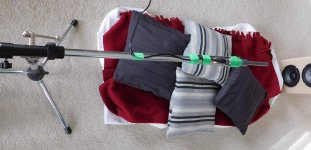
Here are some pics of my setup. It's a standard boom (0.8m) mic with a mic holder and Umik-1. I can accept the comments from the mic measurement article (above) but I think any reflections from the holder will be HF hash that I usually ignore or smooth anyways.
I'll try an experiment to modify the boom as per the article, to see what the effect is.
When I measure. I clear out 1m to either side of the speaker and 2m in front, then gate the measurement.
P.S. Nice avatar change")
Here are some pics of my setup. It's a standard boom (0.8m) mic with a mic holder and Umik-1. I can accept the comments from the mic measurement article (above) but I think any reflections from the holder will be HF hash that I usually ignore or smooth anyways.
I'll try an experiment to modify the boom as per the article, to see what the effect is.
When I measure. I clear out 1m to either side of the speaker and 2m in front, then gate the measurement.
P.S. Nice avatar change
Attachments
Here is an example of how disasterous errror the stand might make! Be warned!

Real problem is reflection from floor, ceiling and walls. Don's speaker is not on a stand and mic is about 1m from the floor. Pillows on the floor help but don't eliminate the problem. We just must learn to recognize reflections and use some brain power to "eQ" them out of analysis..
Loudspeaker measurements
Loudspeaker Measurements
How to measure frequency response of completed loudspeaker at home with accuracy
Loudspeaker frequency response measurement technique
A New Approach to Loudspeaker Measurements | audioXpress

@juhazi - A fine sense of humor , much appreciated, and thanks for the additional links.
@docali - the rug is dense (44oz) with 3/8" high density foam underlay and seems to be good for attenuating MF and HF IMO and according to some acoustics tables. Maybe I should properly characterize it. The ceiling is vaulted (apex 3m).
Lets see what the experiment shows I would like to know.
, much appreciated, and thanks for the additional links.@docali - the rug is dense (44oz) with 3/8" high density foam underlay and seems to be good for attenuating MF and HF IMO and according to some acoustics tables. Maybe I should properly characterize it. The ceiling is vaulted (apex 3m).
Lets see what the experiment shows
I would like to know.
Last edited:
SH402 MF ripple
This is a quick test to find the root cause of the MF ripple I was seeing.
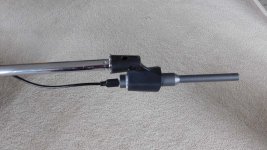
Trial #1 : reconfigure the microphone to reduce possible reflections from the holder. Pic#1 shows the streamlined mic#2 without holder (mic#1) there is some HF improvement but not significant. Measurements are 1/48 octave smoothing and gated [-1,5ms]. It was an easy change but not the cause of the MF ripple. No downside in using this arrangement for future measurements.
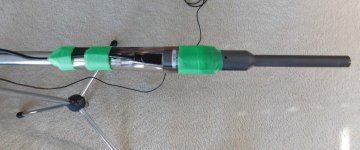
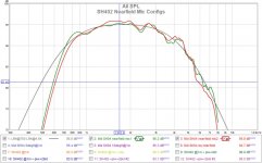
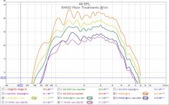
Trial #2 : adding pillows, and blankets on top of the carpet to see if it is residual floor bounce. Pic#3 shows a top view of adding the floor treatments. Pic#4 show the results. I have shifted the curves so they can be compared easily. The more floor treatment, the smoother the curves get, and the lowest curve has 25cm of composite padding. So the ripple is from residual floor bounce and its higher for lower frequency as expected. At higher frequencies the carpet is more effective and the horn vertical polar narrows reducing energy to the floor. Measurements are 1/24 octave smoothing and gated [-1,5ms].
Definitely worth doing
This is a quick test to find the root cause of the MF ripple I was seeing.
Trial #1 : reconfigure the microphone to reduce possible reflections from the holder. Pic#1 shows the streamlined mic#2 without holder (mic#1) there is some HF improvement but not significant. Measurements are 1/48 octave smoothing and gated [-1,5ms]. It was an easy change but not the cause of the MF ripple. No downside in using this arrangement for future measurements.
Trial #2 : adding pillows, and blankets on top of the carpet to see if it is residual floor bounce. Pic#3 shows a top view of adding the floor treatments. Pic#4 show the results. I have shifted the curves so they can be compared easily. The more floor treatment, the smoother the curves get, and the lowest curve has 25cm of composite padding. So the ripple is from residual floor bounce and its higher for lower frequency as expected. At higher frequencies the carpet is more effective and the horn vertical polar narrows reducing energy to the floor. Measurements are 1/24 octave smoothing and gated [-1,5ms].
Definitely worth doing
Attachments
The best pillow filling material are geese feathers. If the pillow is too hard it becomes a problem itself. But my measurement setups often look the same
I am not sure if you mentioned your ir window settings and showed the REW impulse response window for the best setup. Mine often looks like this:

I am not sure if you mentioned your ir window settings and showed the REW impulse response window for the best setup. Mine often looks like this:
Trial #2 : adding pillows, and blankets on top of the carpet to see if it is residual floor bounce. Pic#3 shows a top view of adding the floor treatments. Pic#4 show the results. I have shifted the curves so they can be compared easily. The more floor treatment, the smoother the curves get, and the lowest curve has 25cm of composite padding. So the ripple is from residual floor bounce and its higher for lower frequency as expected. At higher frequencies the carpet is more effective and the horn vertical polar narrows reducing energy to the floor. Measurements are 1/24 octave smoothing and gated [-1,5ms].
Other than the lowest "ripple", it still looks like a diffraction product to me.
My guess is that it's as much a product of the "t" shaped result from the line-array/"stand" + horn, than anything else.
I'd like to see just the horn: in other words either suspended (rope from ceiling) or a center "pole" *stand with some absorptive "wrap" (..a blanket) around that pole.
*like your mic stand.
Last edited:
MF ripple - woofer cabinet diffraction test
Two more good suggestions to try from @ScottG and @Juhazi.
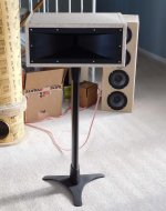
I've put the horn on a narrow stand and removed the woofer cabinet to see what impact it had (pic#1).
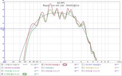
There is some reduction in amplitude (pic#2) but the frequencies where peaks occur are the same. It suggests that some floor bounce might be going backwards because the woofer cabinet is not blocking it.
When I move the mic a bit forward or backward it changes the frequency where ripple peaks occur, suggesting floor bounce.
Two more good suggestions to try from @ScottG and @Juhazi.
I've put the horn on a narrow stand and removed the woofer cabinet to see what impact it had (pic#1).
There is some reduction in amplitude (pic#2) but the frequencies where peaks occur are the same. It suggests that some floor bounce might be going backwards because the woofer cabinet is not blocking it.
When I move the mic a bit forward or backward it changes the frequency where ripple peaks occur, suggesting floor bounce.
Attachments
Last edited:
Measuring axial response at twice the distance will shift floor bounce lower in freq.
Probably not - but maybe if you drill big hole to floor...
Probably not - but maybe if you drill big hole to floor...
Perhaps the reverse then, take a look at the attached thumbnail pic...
but a change anyway!Another thing to remember is that at few hundred Hz (wavelength much more than baffle width) , baffle diffraction doesn't make sudden ripples in response, but baffle loss which is smooth!
An externally hosted image should be here but it was not working when we last tested it.
Attachments
Last edited:
^ agreed, the ripple will be a function of the geometry, frequency and floor material.
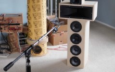
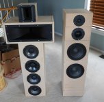
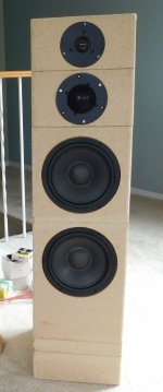
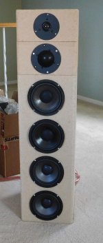
Onward to listening tests to see if I prefer one or maybe a hybrid of the two. The two candidates are shown below. The floor friendly model on the left and the conventional on the right. I've spent the last 2 weeks listening to the left one and now the right one is active. I listen to only one at a time, in the same position, using a generated mono signal.
I've been trying this software Harman - How to Listen to train myself and maybe one of the speakers will reveal more detail to give me a higher score
Attachments
Biggesst difference is in directivity of midrange and highs. This difference will most likely realize when a speaker is set near a corner in the room. The horn-version will have less early reflections and thus smoother room response and better imaging. When placed far from walls (more than 1m, typically along the long wall), there shouldn't be big difference.
I like to check the decay of room response (at listening position). Here are my dipoles with Fountek Neo3.5H as tweeter, and with backside "ambience" tweeter (single speaker playing). And yes it was easy to hear the difference, I liked more the version with ambience tweeter. Later on I switched to dipole tweeter.
I like to check the decay of room response (at listening position). Here are my dipoles with Fountek Neo3.5H as tweeter, and with backside "ambience" tweeter (single speaker playing). And yes it was easy to hear the difference, I liked more the version with ambience tweeter. Later on I switched to dipole tweeter.
Attachments
Last edited:
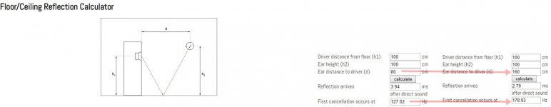
The sound source seems to be nearer to the floor than to the ceiling. I always try to place a pillow on the floor at mid of the distance in order to assess the amount of the floor comb filter.
Here is a good picture from the CLIO Pocket manual.
View attachment 792310
Thanks for the suggestion(s) and the diagram.
I've been looking at that diagram and tried to find the actual gate boundary when the floor bounce disappears. The calculated path delay depends on where the bounce occurs and varies only a small amount (5.5ms -0/+0.5ms) for my setup (0.8m vert, 1.0m horiz). I also get essentially the same curve for gating [0,5], [0,6], [0,7], [0,8] so my MF graphs include the floor bounce which is what I want. I can remove the floor bounce effect by reducing to less than 4 ms. The previous HF tweeter measurements were gated too short to include floor bounce.
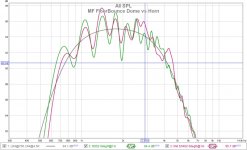
This is an MF comparision between the RS52 dome and HS402 horn measurements gated [0,6ms]. The floor does not care.
Attachments
Last edited:
comparing woofer arrangements
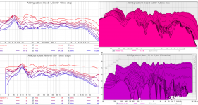
I had a few months to go back and forth several times between my two woofer arrangements. The are both using the same mid RS52 and high DC28 and were EQ'd approx flat at 1m at midrange height. The total Sd is approx the same for both woofer arrangements. The 2x8" goes lower so it needs less sub support, but the 4x6.5" addresses the floor bounce issue.
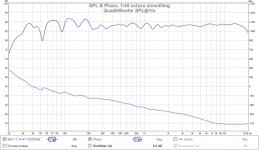
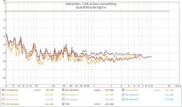
The first 2 graphs are for the 4x6.5" at 1m. There are still some room effects at VLF because I'm only using a single subwoofer in these measurements.
The 4x6.5 is more consistent (even) with distance, sounds cleaner and more detailed. The concept is good enough to invest in better woofers because these budget woofers start sounding muddy when pushed (>95dB@1m) which is OK for the test as I rarely play that loud.
I had a few months to go back and forth several times between my two woofer arrangements. The are both using the same mid RS52 and high DC28 and were EQ'd approx flat at 1m at midrange height. The total Sd is approx the same for both woofer arrangements. The 2x8" goes lower so it needs less sub support, but the 4x6.5" addresses the floor bounce issue.
The first 2 graphs are for the 4x6.5" at 1m. There are still some room effects at VLF because I'm only using a single subwoofer in these measurements.
The 4x6.5 is more consistent (even) with distance, sounds cleaner and more detailed. The concept is good enough to invest in better woofers because these budget woofers start sounding muddy when pushed (>95dB@1m) which is OK for the test as I rarely play that loud.
Attachments
- Home
- Loudspeakers
- Multi-Way
- Modular active 3 way - work in progress