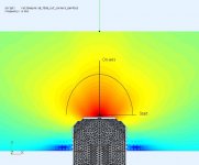
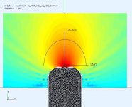
Back to rounded edges and a shallow waveguide. That looks good, I might change the waveguide a little to widen the horizontal. I probably could get away with less radius on the corners. I could even build that as well. It seems to be a popular design approach for a good reason ")
Attachments
Last edited:
I haven't slept in two days so I'm just spitballing.
Wouldn't putting the thing off center also help?
Well... shrooms can do that
I have tried offsetting drivers and it causes asymmetric polar response which I don't want. It sounds fine in the sweet spot but IMO makes it smaller as well. You also end up with specific right and left speakers builds.
And metrics: Just do a stupid simple one, subtract your polar plot of tweeter from polar plot of mid, sum the differences. Your script will try to minimize that sum.
I understand what you're suggesting, and the concept is fair for a limited #variables. The problem is the large number of variables required to generate the physical model, and the intermediate processing steps to actually get that model into a mesh format that ABEC could use. Each run on ABEC could take 30 min or more. So I try to get some insight into what direction I should take by trying different shapes. I'm starting to build some intuition to what might work and the last sim seems to be in the ball park.
Last edited:
Note: just because it looks good on a polar, doesn't mean it will sound better.
I can accept that. I was trying to get a clean wavefront to start with.
There are reasons why that weird upper freq. off-axis flair could be beneficial, and why you would NOT want a more directive response (though more uniform).
There's lots of weird here. Which weird and in which post?
The reason why it could be beneficial is that we increasingly loose "sensitivity" to off-axis pressure (depending on the bandwidth), and it could be advantageous to effectively "compensate" for this.
Note: we are most sensitive horizontally +/- 30 forward AND rearward (particularly 1.5 kHz to about 7 kHz with emphasis in this bandwidth for localization).
Another reason (again bandwidth dependent) is to "steer" pressure differences (Horizontally) for improved lateral results in one respect or another.
Last edited:
That would be true, if for some reason, my sim did not reflect the actual driver performance. That the system's actual off axis perf is different than predicted.
I'd have to measure a system that's built with the intended baffle, extract the differences from the equivalent model's prediction, then rework the baffle to provide that difference (ie. compensation). It could be done and would probably be the only way to fix the horizontal polar. At least I have some examples of what happens when you tinker with the baffle.
I plan on building post#84 (or something close to it) so we shall see when its measured.

#84 Back to rounded edges and a shallow waveguide. That looks good, ...
I plan on building post#84 (or something close to it) so we shall see when its measured.
Take a look at the datasheet for the Wavecor TW030WA11/12 30 mm textile tweeter with waveguide, 4/8 ohm. It is used in a few new speakers crossed at relatively low frequencies to 7" and 8" midbass for smooth constant directivity over the crossover range.
Amp and crossover changes
I finally had a chance to make some changes to my amp and crossover.
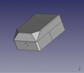
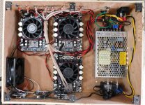
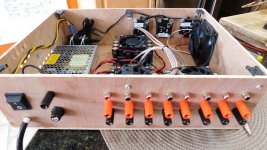
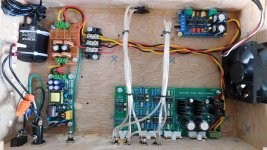
The Amp box (pics #1,#2) now has 6 channels with space for another 2 channels (1 module). The amp boards are Sure TriPath stereo modules with the volume attenuator. I use the volume attenuator to compensate for driver sensitivity differences and the mute control for testing. The speakers are silent when I short the amp inputs. I also like the way they sound.
The crossover (pic#3) has a LC power filter (4th order) added to reduce the SMPS noise. It does that effectively but there is still some minor broadband noise left in the <500Hz that I can hear when I'm close to the speaker. I can't hear it at the listening position (2m). It currently only has 1 subwoofer bandpass filter installed, as I'm still waiting for the second one to arrive.
Both units have quiet low speed case fans for cross flow cooling. The Sure modules also have fans but they never turn on when the case fan is running.
I finally had a chance to make some changes to my amp and crossover.
The Amp box (pics #1,#2) now has 6 channels with space for another 2 channels (1 module). The amp boards are Sure TriPath stereo modules with the volume attenuator. I use the volume attenuator to compensate for driver sensitivity differences and the mute control for testing. The speakers are silent when I short the amp inputs. I also like the way they sound.
The crossover (pic#3) has a LC power filter (4th order) added to reduce the SMPS noise. It does that effectively but there is still some minor broadband noise left in the <500Hz that I can hear when I'm close to the speaker. I can't hear it at the listening position (2m). It currently only has 1 subwoofer bandpass filter installed, as I'm still waiting for the second one to arrive.
Both units have quiet low speed case fans for cross flow cooling. The Sure modules also have fans but they never turn on when the case fan is running.
Attachments
Residual noise source - found
After some experiments.
It turns out the minor noise, that I thought was coming from the crossover, is actually coming from my PC soundcard. When I short the crossover inputs the system is silent. When I use a different soundcard (RPI with Piano2.1) the system is silent.
After some experiments.
It turns out the minor noise, that I thought was coming from the crossover, is actually coming from my PC soundcard. When I short the crossover inputs the system is silent. When I use a different soundcard (RPI with Piano2.1) the system is silent.
two woofers in one chamber
I've noticed the midbass starts to get muddy when the volume is turned up (>96dBc@1m. There are a few things that could cause this so I thought I'd make a few woofer specific measurements, try a few mods and post the results before I change the woofers.
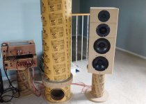
Possible suspects 1) budget woofers @$12US each, 2) common chamber for 2 woofers, 3) damping material insufficent, 4) baffle issues, 5) AMPs, etc. My test setup is shown in pic#1.
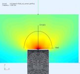
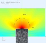
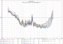
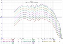
First test is to see if the SPL profile or THD profile changes with amplitude. Pics#2, #3 show the SPL is linear but there is a problem with distortion. There is a THD peak around 250Hz that looks wrong. This could be the drivers or interactions from the common chamber arrangement.
Second test is to check the model using the results of HornResp sim. The system Qts=1.05 which is higher than I'd prefer but still OK. The TC6028 has Xmax=3mm and this is reached for 2 parallel drivers when V=~9vrms or (9vrms*9vrms/4ohm)=~20watts and since I only need 2W for 96dB @ 1m I don't think I'm exceeding Xmax.
I've noticed the midbass starts to get muddy when the volume is turned up (>96dBc@1m. There are a few things that could cause this so I thought I'd make a few woofer specific measurements, try a few mods and post the results before I change the woofers.
Possible suspects 1) budget woofers @$12US each, 2) common chamber for 2 woofers, 3) damping material insufficent, 4) baffle issues, 5) AMPs, etc. My test setup is shown in pic#1.
First test is to see if the SPL profile or THD profile changes with amplitude. Pics#2, #3 show the SPL is linear but there is a problem with distortion. There is a THD peak around 250Hz that looks wrong. This could be the drivers or interactions from the common chamber arrangement.
Second test is to check the model using the results of HornResp sim. The system Qts=1.05 which is higher than I'd prefer but still OK. The TC6028 has Xmax=3mm and this is reached for 2 parallel drivers when V=~9vrms or (9vrms*9vrms/4ohm)=~20watts and since I only need 2W for 96dB @ 1m I don't think I'm exceeding Xmax.
Attachments
two woofers two chambers
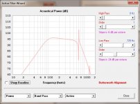
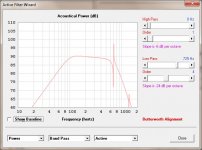
I separated the woofers and each has their own chamber (~10L). The partition slightly reduced the chamber volume. The HornResp sim is in pic#1.
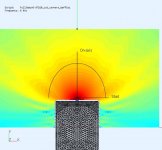
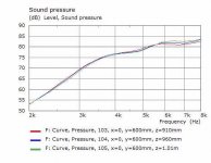
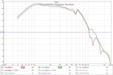
The two woofers are close in performance but not exact as shown in the nearfield measurement in pic#2. I have 1cm acoustic tile mounted to the rear chamber but it still has some residual reflections so I added 8cm fiberglass to further quiet reflections and comparison is in Pic#3.
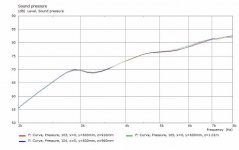
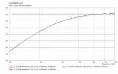
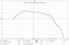
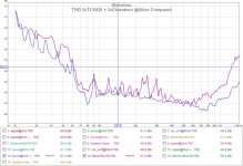
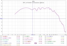
Pic#4 shows THD for 2 woofers@60cm compared to 1 woofer@0cm. This time the results are close enough and it sounds much better. Pic#5 has the 2 woofer SPL curve @60cm.
I separated the woofers and each has their own chamber (~10L). The partition slightly reduced the chamber volume. The HornResp sim is in pic#1.
The two woofers are close in performance but not exact as shown in the nearfield measurement in pic#2. I have 1cm acoustic tile mounted to the rear chamber but it still has some residual reflections so I added 8cm fiberglass to further quiet reflections and comparison is in Pic#3.
Pic#4 shows THD for 2 woofers@60cm compared to 1 woofer@0cm. This time the results are close enough and it sounds much better. Pic#5 has the 2 woofer SPL curve @60cm.
Attachments
I've noticed the midbass starts to get muddy when the volume is turned up (>96dBc@1m....
The system Qts=1.05 which is higher than I'd prefer but still OK.
Maybe try a deeper enclosure to lower Qtc?
What excursion are you hitting with the woofers at 96dB?
At 96dBc @1m I'm only using 2W and the woofers are only moving 1mm or so. I'm not exceeding Xmax and it started sounding muddy. I'm convinced it was from 2 drivers interacting in the common chamber.
I would probably make the next cabinet taller rather than deeper to limit reflections from the back wall. Originally I had the one 6.5" driver in a 20L cabinet for Qtc=0.8 . I reused the cabinet and added the second driver.
Next cabinet is for 2 x 8" drivers and Qtc=0.8
I would probably make the next cabinet taller rather than deeper to limit reflections from the back wall. Originally I had the one 6.5" driver in a 20L cabinet for Qtc=0.8 . I reused the cabinet and added the second driver.
Next cabinet is for 2 x 8" drivers and Qtc=0.8
At 96dBc @1m I'm only using 2W and the woofers are only moving 1mm or so. I'm not exceeding Xmax and it started sounding muddy. I'm convinced it was from 2 drivers interacting in the common chamber.
I would probably make the next cabinet taller rather than deeper to limit reflections from the back wall. Originally I had the one 6.5" driver in a 20L cabinet for Qtc=0.8 . I reused the cabinet and added the second driver.
Next cabinet is for 2 x 8" drivers and Qtc=0.8
When I read your post I starting wondering if you are getting internal reflected sound re-radiating out the cones. This can be a source of "muddiness". The solution is to try to adsorb as much of the backwave as possible.
Making the cabinet taller will only move internal resonances to a lower frequency which is yet another problem. How much absorptive material do you have inside the cabinet?
One solution that you might be able to try with the current cabinet would be to put in a baffle to divide the compartment with the two drivers into two equal volume compartments and increase stuffing levels. The resonances are moved up in frequency where the stuffing will be more effective. Also, adding specialized 1" thick damping sheets to the walls can help alot in this regard, but it's not cheap. For example:
Sonic Barrier 3/4" 3-Layer Acoustic Sound Damping Material with PSA 18" x 24"
Thanks Charlie, that was also one of my suspicions as well. Thanks for the material link.
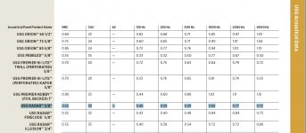
HornResp unmasked shows the basic reflections from the rear chamber. After I separated the woofers chambers I measured the nearfields and adjusted the damping material to eliminate internal reflections. I used 1.5cm acoustic tile glued to the back with acoustic sealant and then put 8cm of fiberglass in front of the tile. The nearfield graphs SPL and THD show the reflections are eliminated. The tile spec USG Radar R2120 is below. I also think there was some asymmetry related THD caused by using the initial single chamber.
The woofers sounds much better now with separate chambers and more damping material. I need a chance to push to volume before I'm satisfied. That being said, I'll still prepare another dual chamber box with 8" woofers for comparison.
Attachments
Last edited:
- Home
- Loudspeakers
- Multi-Way
- Modular active 3 way - work in progress