Interestingly. The first time I saw the IR for a passive LR4 , I spent at least a week (with DIYaudio help) trying to determine what was wrong with it. It turned out it was suppose to look like that by design. I even measured 4 different commercial speakers that I own (and like) and all of them had very messy IR and steps.
Is that for three ways, or two ways as well? My two way with 4th order bessel acoustic slopes seems to have a pretty reasonable (to my limited understanding) step response....
Tony.
It was both 2 way and 3 way, but the 3 way was worse. Have a look OmniDirectional - work in progress It was a surprise to me.
The passive LR4 was in my 2 way at OmniDirectional - work in progress
The passive LR4 was in my 2 way at OmniDirectional - work in progress
Yes, the phase compensation is mostly time aligning the driver outputs after all the gain EQ and XO induced delays.
The IR and Step of single drivers are relatively good (but not perfect). I implement separate gain and phase compensations even though they could be combined. The gain adjustments are via equalizer and the effects (if >2dB) are easily noticed when you turn them on/off. The phase compensation is unity gain via FIR convolution and can also be separately turned on/off. However, I find the phase compensation effects much harder to describe because they show up in more subtle ways. Acoustic instruments seem a little more real (detail, attack), if that makes any sense. BTW I still like my commercial speakers even after I measured and discovered their "flaw".")
I might try moving the speaker sections forward/backward to see if I can "manually" time align the drivers. I see some speakers where they align the voice coils vertically.
Late post : I only have one test speaker now. So I can't comment on other important phase related details like imaging and sound stage.
The IR and Step of single drivers are relatively good (but not perfect). I implement separate gain and phase compensations even though they could be combined. The gain adjustments are via equalizer and the effects (if >2dB) are easily noticed when you turn them on/off. The phase compensation is unity gain via FIR convolution and can also be separately turned on/off. However, I find the phase compensation effects much harder to describe because they show up in more subtle ways. Acoustic instruments seem a little more real (detail, attack), if that makes any sense. BTW I still like my commercial speakers even after I measured and discovered their "flaw".
I might try moving the speaker sections forward/backward to see if I can "manually" time align the drivers. I see some speakers where they align the voice coils vertically.
Late post : I only have one test speaker now. So I can't comment on other important phase related details like imaging and sound stage.
Last edited:
Yes it would be interesting to see whether physical time alignment will bring the step response close to what you have achieved with the FIR. I've read that to get a step response like your corrected one you need a transient perfect crossover, which I don't think you can do except with first order? So I'm interested to see results of any experiments you do
edit: doing a bit of searching after posting, it would appear that 2nd order LR are actually transient perfect, but higher orders not so.
Tony.
edit: doing a bit of searching after posting, it would appear that 2nd order LR are actually transient perfect, but higher orders not so.
Tony.
Last edited:
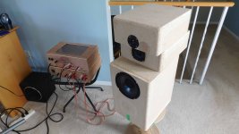
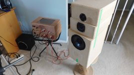
driver jenga
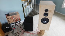
I was curious to see if I could effect the same IR & Step cleanup by shifting the drivers to time align them. The problem is a single distance but the wavelength variation is infinite. Pics#1*#2 show the drivers are shifted in the Z-axis only.
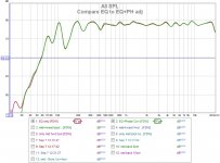
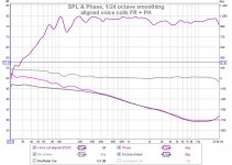
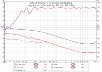
Pic#3 is the FR with EQ only, then overlaid with the EQ+PH corrections on. You can see that I can change phase without effecting the FR shape.
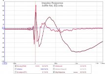
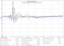
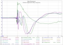
Pic#4 & #5 are a comparison with flat baffle vs voice coil alignment. It makes a little difference but not much. I require more phase adjustment than simple driver shifting can provide. It also is causing more diffraction and a bumpy FR from the front steps. Pic#6 & #7 are just some variations in IR and Step from various combinations that I tried. Notice aligning VC's is a move in the right direction but it's not enough and it would only be the right correction for a narrow band(s) of frequencies.
I was curious to see if I could effect the same IR & Step cleanup by shifting the drivers to time align them. The problem is a single distance but the wavelength variation is infinite. Pics#1*#2 show the drivers are shifted in the Z-axis only.
Pic#3 is the FR with EQ only, then overlaid with the EQ+PH corrections on. You can see that I can change phase without effecting the FR shape.
Pic#4 & #5 are a comparison with flat baffle vs voice coil alignment. It makes a little difference but not much. I require more phase adjustment than simple driver shifting can provide. It also is causing more diffraction and a bumpy FR from the front steps. Pic#6 & #7 are just some variations in IR and Step from various combinations that I tried. Notice aligning VC's is a move in the right direction but it's not enough and it would only be the right correction for a narrow band(s) of frequencies.
Attachments
-
 DSCN5486r.jpg516.8 KB · Views: 773
 -
 DSCN5487r.jpg528.3 KB · Views: 760
 -
 Compare EQ to EQ+PH adj.jpg100 KB · Views: 744
 -
 baffle flat, EQ only.jpg87.8 KB · Views: 710
 -
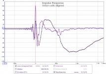 Voice coils aligned.jpg86.5 KB · Views: 709
 -
 Various alignment Impulse response.jpg99.6 KB · Views: 204
 -
 Various alignment Step response.jpg110.5 KB · Views: 214
This is the graph for aligning the voice coils and is very similar to the aligned to baffle graph. You can see the amount of phase adjustment required to get back to a min phase response.
The LR4 may be phase aligned, but not in the same cycle. The LP shift is +360deg (4 * 90deg per order) and the HP is shifted -360deg, so there is a 2 cycle difference (-720deg LP to HP), even if they are "in phase".
Interestingly, you can select a distance that causes two drivers to be out of phase at a particular frequency and generate a null. Might come in handy for resonant drivers.
Late post : sometimes REW is off by a cycle, so in the 2nd graph the min phase should be centered on 0deg not -360deg (diff 1 cycle) and same with excess phase is sometimes 360deg (1 cycle) off. Don't know how to adj it, as all the curves move when you "add phase, +/-360deg".
Attachments
Last edited:
REW unwraps the phase based on the cursor position is when the phase is wrapped. In the charts above it appears the cursor was at 20Hz when the phase was unwrapped.
The desired result should be achieved if the cursor position is nearer the top of the frequency range when the phase is unwrapped. Try 10kHz instead of 20hz.
The desired result should be achieved if the cursor position is nearer the top of the frequency range when the phase is unwrapped. Try 10kHz instead of 20hz.
Adding a single sub + RPI
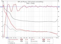
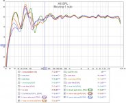
Next up, filling in the VLF by adding a single subwoofer (pic#1). I have room modes that are hard to suppress with only 1 sub (pic#2). I can get better (more even) with 2 subs, except I'm short an amp channel until I build in more. I used a PDR10 (built in amp) to start filling in the VLF. Pic#3 show the variation as I move the single sub around (within 1m dia circle). Sounds much better but it needs my other sub (BP6).
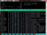
Then I moved the EQ and FIR filters over to my RPI3B. It's a headless and wireless media player running Volumio (player), Ecacound (EQ), and Brutefir (FIR). It's currently running its Piano DAC in 2.0 mode so I can use my analog sub bandpass. Attached pic shows light CPU loading on the 4 cores.
Next up, filling in the VLF by adding a single subwoofer (pic#1). I have room modes that are hard to suppress with only 1 sub (pic#2). I can get better (more even) with 2 subs, except I'm short an amp channel until I build in more. I used a PDR10 (built in amp) to start filling in the VLF. Pic#3 show the variation as I move the single sub around (within 1m dia circle). Sounds much better but it needs my other sub (BP6).
Then I moved the EQ and FIR filters over to my RPI3B. It's a headless and wireless media player running Volumio (player), Ecacound (EQ), and Brutefir (FIR). It's currently running its Piano DAC in 2.0 mode so I can use my analog sub bandpass. Attached pic shows light CPU loading on the 4 cores.
Attachments
Last edited:
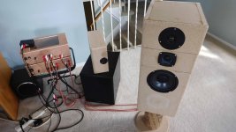
trying a different tweeter, DC28F
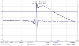
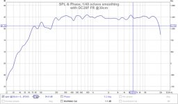
After a week of listening its time to change the configuration and try a new tweeter. I did like the previous configuration (TD20F tweeter) and would like to compare it to another (DC28F tweeter) that I have. The DC28F has a large faceplate that I did not remove, and it results in a large 10cm C-C spacing from the midrange.
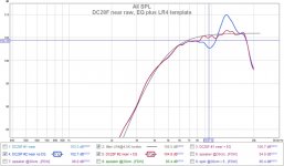
Pic#1 shows the top slice that was replaced. The new tweeter (DC28F) was EQ'd to flatten it and there's a LR4 template curve @4.5KHz for comparison. I have 2 of these tweeters and they both measure the same. The entire speaker's FR (without sub) measured at 30cm to check the integration. Interestingly, I did not adjust the FIR phase adjustment, I reused the last one, and it came out reasonable looking.
After a week of listening its time to change the configuration and try a new tweeter. I did like the previous configuration (TD20F tweeter) and would like to compare it to another (DC28F tweeter) that I have. The DC28F has a large faceplate that I did not remove, and it results in a large 10cm C-C spacing from the midrange.
Pic#1 shows the top slice that was replaced. The new tweeter (DC28F) was EQ'd to flatten it and there's a LR4 template curve @4.5KHz for comparison. I have 2 of these tweeters and they both measure the same. The entire speaker's FR (without sub) measured at 30cm to check the integration. Interestingly, I did not adjust the FIR phase adjustment, I reused the last one, and it came out reasonable looking.
Attachments
tweeters compared
I level adjusted and flattened the FR before comparing these tweeters. There is nothing dramatically different between them and both sound good to me. I do think the TD20 is slightly better sounding and only because I can get it closer to the midrange.
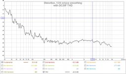
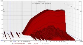
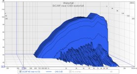
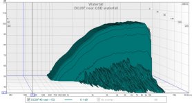
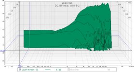
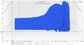
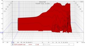
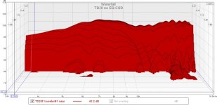
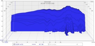
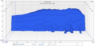
I posted a couple of near field waterfalls for these drivers with my XO in place. The first 2 are the drivers with no EQ drivers, and the last one is DC28F with EQ.
I can't extract any insight from them. Except maybe that EQ does not change the underlying resonances in the driver, because the CSD tail is not effected by EQ.
I level adjusted and flattened the FR before comparing these tweeters. There is nothing dramatically different between them and both sound good to me. I do think the TD20 is slightly better sounding and only because I can get it closer to the midrange.
I posted a couple of near field waterfalls for these drivers with my XO in place. The first 2 are the drivers with no EQ drivers, and the last one is DC28F with EQ.
I can't extract any insight from them. Except maybe that EQ does not change the underlying resonances in the driver, because the CSD tail is not effected by EQ.
Attachments
Hi Don, you need to use different settings. the defaults are for room modes. attached are the settings I use to try and get plots like stereophiles.
This was for a dms37 tweeter outside at 1M.
Only put in 25db range from the speaker measurement too.
Tony.
This was for a dms37 tweeter outside at 1M.
Only put in 25db range from the speaker measurement too.
Tony.
Attachments
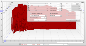
They look pretty good. Change your limits so that lower db is 70 rather than 60. No obvious tesonances present.
Some info here Measuring Loudspeakers, Part Two Page 5 | Stereophile.com
Tony.
Some info here Measuring Loudspeakers, Part Two Page 5 | Stereophile.com
Tony.
Last edited:
comparing CSDs
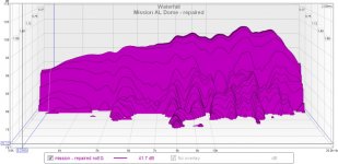
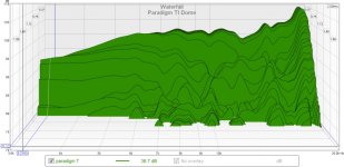
Thanks Tony for the link. I read all 3 parts and a bunch of other stuff and had a look at other tweeter CSDs. My settings are tweaked a bit more [Slices=60, Range=2ms, Window=5ms, Rise=0.2]. All graphs use the same settings and SPL.
I also included the results from a few more tweeters. The TD20 and DC28 look fine. I was surprised at the Paradigm titanium dome because I was expecting better and Mission aluminum dome (repaired) because I was expecting worse.
Attachments

- Home
- Loudspeakers
- Multi-Way
- Modular active 3 way - work in progress