I'm still pondering why there is a difference in the midrange.
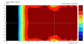
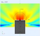
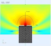
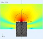
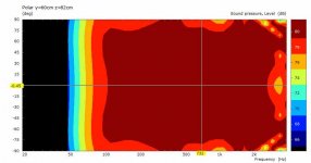
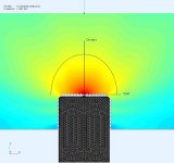
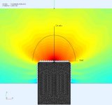
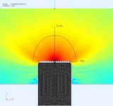
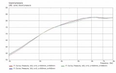
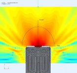
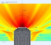
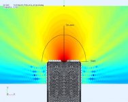
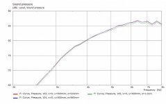
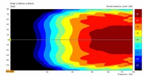
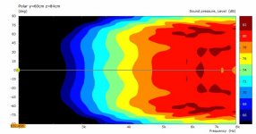
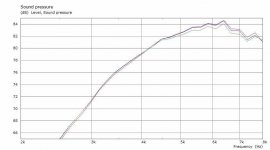
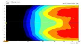
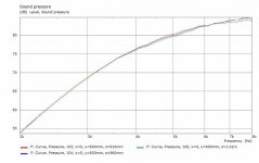
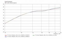
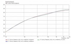
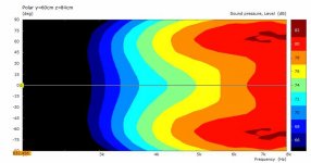
These are some simulations comparing the polar responses. Both the RS52 and PC83 are similar up to about 3Khz, then the PC83 cone starts to lobe. The RS52 polar has more "pinch" at the XO point which I think because of its large faceplate and I can't get it as close to the top woofer as a PC83.
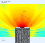
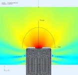
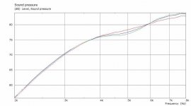
The first set are the RS52AN then the PC83, both with dual woofers TC6028. Two posts to compare them.
These are some simulations comparing the polar responses. Both the RS52 and PC83 are similar up to about 3Khz, then the PC83 cone starts to lobe. The RS52 polar has more "pinch" at the XO point which I think because of its large faceplate and I can't get it as close to the top woofer as a PC83.
The first set are the RS52AN then the PC83, both with dual woofers TC6028. Two posts to compare them.
Attachments
A very simple and basic thing - a dome and a cone have totally different radiation pattern, starting when wavelength gets smaller that diameter. When we go higher even smaller details like profile, stiffness, surround roll, dustcap, phase shield etc. make a difference.
Most simulations use only piston model with variable diameter. Does ABEC simulate membrane profile?
A poster by Klippel https://www.klippel.de/fileadmin/_migrated/content_uploads/KLIPPEL_Sound_Radiation_Poster_01.pdf
Most simulations use only piston model with variable diameter. Does ABEC simulate membrane profile?
A poster by Klippel https://www.klippel.de/fileadmin/_migrated/content_uploads/KLIPPEL_Sound_Radiation_Poster_01.pdf
Last edited:
A very simple and basic thing - a dome and a cone have totally different radiation pattern, starting when wavelength gets smaller that diameter. When we go higher even smaller details like profile, stiffness, surround roll, dustcap, phase shield etc. make a difference.
I agree with your general comments on drivers and radiation.
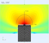
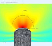
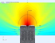
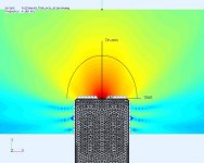
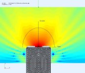
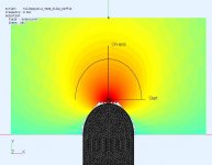
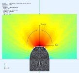
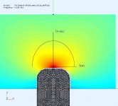
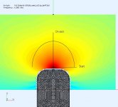
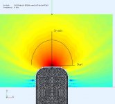
My midrange is 725Hz-4550Hz with LR4 on both sides. Both drivers are well behaved in this range as shown in the previous measurements of FR and CSD waterfalls. The question is "why do I prefer the dome"? A BEM sim is a way to look at the entire field pattern and both drivers look very similar up to 3Khz. The cone (70mm) starts to lobe (@>3Khz) before the dome (52mm). In my midrange band the difference is not enough to say the dome should sound better.
Most simulations use only piston model with variable diameter. Does ABEC simulate membrane profile?
A poster by Klippel https://www.klippel.de/fileadmin/_migrated/content_uploads/KLIPPEL_Sound_Radiation_Poster_01.pdf
Yes, the membrane shape is modeled. Membrane misbehaviour (ala Klippel) could be included if I had data, but my CSDs indicate the drivers are well behaved in my midrange. Post#60 provides the level of detail used to model a driver. The actual cabinet size, panel thickness and roundovers are also included in the model. The XO is also included.
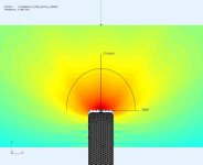
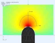
I noticed that the horizontal wavefront begins to change in the 3-4Khz region. Its no longer a nice rounded expansion.
I cross to the tweeter at 4.5KHz and I was trying to get a better wavefront shape by trying a few ideas.
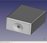
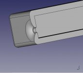
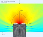
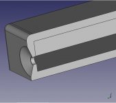
This is the first trial using a 20mm dome (not shown in first pic) with a 3mm relief chamfer around the dome. Its not too bad for the simplest solution.
I cross to the tweeter at 4.5KHz and I was trying to get a better wavefront shape by trying a few ideas.
This is the first trial using a 20mm dome (not shown in first pic) with a 3mm relief chamfer around the dome. Its not too bad for the simplest solution.
Attachments
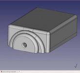
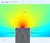
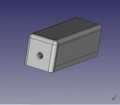
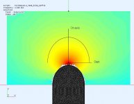
... then my 60 second waveguide. Its a 80mmx100mm ellipse with 10mm depth, lofted up from a 20mm circle. I plan on parameterizing a waveguide model for a proper expansion. This was a quick trial.
Attachments
Last edited:
... then changing the baffle to make it progressive with steps that I could easily make without a CNC or 3D printer. Just seeing where it leads. Lots of lobes.
Attachments
Last edited:
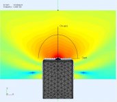
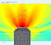
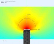
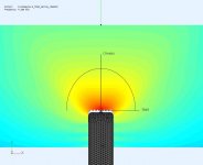
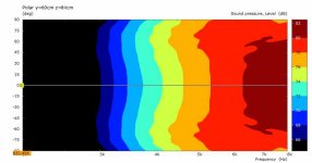
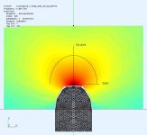
..another one. This time using an elliptic curve, rotated (OD=8omm), 10mm deep, and cut from the front wall to form the WG. There is a 2mm clearance around the 20mm dome. Definitely focuses more power on the axis, and the wave front is well behaved, but I suspect its a bit too narrow as seen in the polar plot.
Attachments
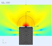
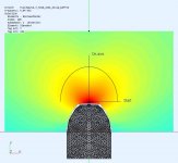
A few tweaks on the ellipse with conical sides (circle lofted into an ellipse). Ellipse is 40mmx80mmx10mm deep. Added 2mm clearance around the dome. It has a wider horizontal polar now.
Attachments
Sometimes I see a tweeter in a smaller "doghouse" sitting atop a larger cabinet. The baffle width is significantly narrowed (120mm) but using the same R14 roundovers. It's not that much different than the wider baffle trial. I think diffraction from the R14 edges is causing ripples in the wavefront. There is also a minor dip forming in the polar response from a narrower, more symmetric baffle. The message is use more rounding ") .
.
.Attachments
.. . and putting a ellipse as the baffle shape. The wavefront looks very good as expected.
Attachments
..It would take less time if there were a good video series on ABEC3 instead of deductive learning via it's examples.
..I'm getting to like ABEC the more I use it, and the more "tool" like it becomes for me.
-I'm going to have to nominate you for this task.

...maybe at some point.
Possibly when I stop discovering new things about ABEC3.
..oh cr@p, that's going to take foreeeeeeeeeeeeeeeeeeeeeeeeeeeeeeeeeeeeeeeeeeeeeeeeeeeeeeeeeeeeeeeeeeeeeeeeeeeeeeeeeeeeeeeeeeeeeeeeeeeeeeeeeeeeeeeeeeeeeeeeeeeeeeeeeeeeeeeeeeeeeeeeeeeeeeeeeeeeeeeeeeeeeeeeeeeeeeeeeeeeeeeeeeeeeeeeeeeeeeeeeeeeeeeeeeeeeeeeeeeeeeeeeeeeeeeeeeeeeeeeeeeeeeeeeeeeeeeeeeeeeeeeeeeeeeeeeeeeeeeeeeeeeeeeeeeeeeeeeeeeeeeeeeeeeeeeeeeeeeeeeeeeeeeeeeeeeeeeeeeeeeeeeeeeeeeeeeeeeeeeeeeeeeeeeeeeeeeeeeeeeeeeeeeeeeeeeeeeeeeeeeeeeeeeeeeeeeeeeeeeeeeeeeeeeeeeeeeeeeeeeeeeeeeeeeeeeeeeeeeeeeeeeeeeeeeeeeeeeeeeeeeeeeeeeeeeeeeeeeeeeeeeeeeeeeeeeeeeeeeeeeeeeeeeeeeeeeeeeeeeeeeeeeeeeeeeeeeeeevr.
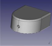
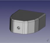
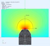
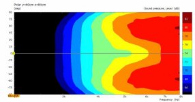
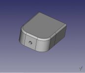
The round front is nice but there needs to be a flat surface to mount the driver. So I tried to make a hybrid using a faceted front with round overs. The driver flat is 100mm, and you can see in the wavefronts and polar it causes a -2dB axial dip from 4.5K-7K just like the doghouse earlier. Maybe it can be corrected by facet angle and size.?
Attachments
Looks to me like something a phaseplug would help with. Throw everything at it, phaseplug and waveguide.
I'm not familiar with ABEC, but what you're doing looks like something a genetic algorithm would be perfect for. Any way to script the mesh generation and feedback the results from ABEC to the mesh generation program? Well, I'm sure there's a way, just wondering if there's an "easy" way.
I'm not familiar with ABEC, but what you're doing looks like something a genetic algorithm would be perfect for. Any way to script the mesh generation and feedback the results from ABEC to the mesh generation program? Well, I'm sure there's a way, just wondering if there's an "easy" way.
hmm.. a phase plug in front of the dome. Good idea, and I have seen that done before so I should give it a try. I still have a few other ideas to try, based on what I've seen in other speakers.
The problem with scripting is that I'd have to have a set of metrics to converge on. Right now I'm just looking at the quality of the field in 2 planes and the horizontal polar needed to match my midrange.
The problem with scripting is that I'd have to have a set of metrics to converge on. Right now I'm just looking at the quality of the field in 2 planes and the horizontal polar needed to match my midrange.
Last edited:
The faceted front edge doesn't work too well but I still need a flat mounting point. The effect from small flat mount area seems to be appearing again, and more rounding does not save it.
Attachments
- Home
- Loudspeakers
- Multi-Way
- Modular active 3 way - work in progress