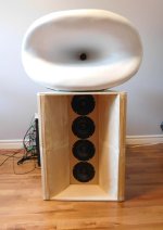
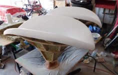
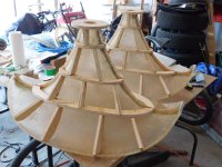
Finally had some time to create the WN270 skins that I need. They still need trimming, stiffening, damping and painting. With the R45mm round over blended in, the overall horn is W84 x H50 x D53 cm.
Attachments
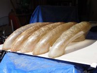
WN270 build pics
A few changes from the way the previous WN425 was assembled. The sand was replaced with recycled glass sandblasting grit 20-30 because the grains are more uniform in size, cleaner, with much less dust. The outer walls are covered in RockWool to help dampen as well as absorb in both directions w.r.t outer wall. The horn radiates from the front and absorbs from the back.
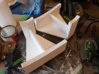
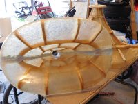
pic1 - 1/2 shells glued together and seam filled
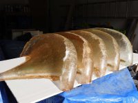
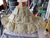
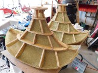
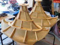
pic2 - plywood ribs added to strengthen the skin
pic3 - another layer of fiberglass mat and resin to bond the ribs in
pic4 - front view of rib structure
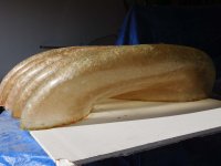
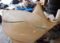
pic5 - damping and mass added using silicone plus sandblasting glass grit 20-30
pic6 - surface painted for looks, and helps find surface detects
pic7 - more damping and absorption added with RockWool Safe-N-Sound fill
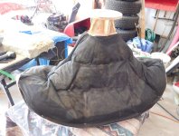
pic8 - RockWool is pressed to the surface and held in place using poly garden fabric (breathable, coarse weave)
pic9 - simple stand for the horns (missing rubber weather stripping for isolation)
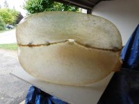
pic10- WN270 on top of my woofer horn, to show its size
Attachments
-
 pic10-DSCN0917r.jpg74.7 KB · Views: 131
 -
 pic9-DSCN0891r.jpg140.3 KB · Views: 134
 -
 pic8-DSCN0901r.jpg153.4 KB · Views: 115
 -
 pic7-DSCN0902r.jpg203.7 KB · Views: 108
 -
 pic6-DSCN0896r.jpg125 KB · Views: 111
 -
 pic5-DSCN0889r.jpg217.5 KB · Views: 116
 -
 pic4-DSCN0886r.jpg159.3 KB · Views: 111
 -
 pic3-DSCN0885r.jpg163.6 KB · Views: 105
 -
 pic2-DSCN0881r.jpg158.3 KB · Views: 108
 -
 pic1-DSCN0873r.jpg144.3 KB · Views: 127

Thanks, I was listening to them last night. They are vivid, and I'm very happy with the design. Going bigger was worth it  . Measurements will be coming soon. I also need to determine (via measurements) if the horn stiffening / damping / absorption was sufficient.
The bass horn will get bigger after it's new fiberglass skin is added. It will look like a 1/2 ellipse with side roundovers to match the top horn, making it wider and deeper. I have enough bass power and I still want the floor mirror effect from a mini woofer array.
. Measurements will be coming soon. I also need to determine (via measurements) if the horn stiffening / damping / absorption was sufficient.The bass horn will get bigger after it's new fiberglass skin is added. It will look like a 1/2 ellipse with side roundovers to match the top horn, making it wider and deeper. I have enough bass power and I still want the floor mirror effect from a mini woofer array.
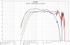
A few initial measurements of the WN270 + DE75TN.
The on axis FR (no smoothing, gated 6ms @1m). I currently listen with the XO LR4 [500-7Khz] because its the same as the previous setups for comparison. But it looks like I could go as low as 300Hz and cover the most sensitive hearing band (ie. ISO226) from a single source. Would be an interesting comparison test.
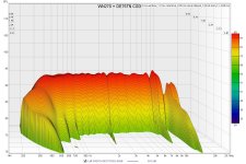
The CSD is also clean, so I think I have a reasonable horn construction. It's also featherweight at 7Kg (horn only). The driver starts misbehaving >10Khz, which could be solved with a more exotic driver (diaphragm material, design or coatings).
The on axis FR (no smoothing, gated 6ms @1m). I currently listen with the XO LR4 [500-7Khz] because its the same as the previous setups for comparison. But it looks like I could go as low as 300Hz and cover the most sensitive hearing band (ie. ISO226) from a single source. Would be an interesting comparison test.
The CSD is also clean, so I think I have a reasonable horn construction. It's also featherweight at 7Kg (horn only). The driver starts misbehaving >10Khz, which could be solved with a more exotic driver (diaphragm material, design or coatings).
Attachments
Last edited:
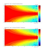
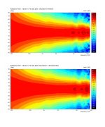
Effect of a backside absorber on the intended horn polars
The primary purpose of the RockWool covering the outside of the WN270 horn was to reduce unintentional acoustic radiation (mechanical vibrations) and provide additional mechanical damping. It also will absorb some external radation (room reflections) as a bonus. I ran some Akabak simulations with the outside of the horn using an acoustic absorbing layer to see how it hypothetically effected the intended polars. Rockwool publishes absorption data for their SafeNSound products which was used in the Akabak simulation. Only the lower freq sound bends around the horn roundover and that will contribute to the polar pattern.
It's acoustic effect can be seen, but it's a minimal improvement, and is primarily seen <500Hz which is expected.
Attachments
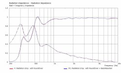
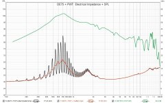
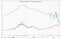
Impedance : WN270 vs PWT with DE75TN
These are some impedance measurements of the WN270 + DE75TN compared to the PWT + DE75TN.
Pic1 : this is the standard impedance graph comparing the DE75TN on/off the WN270 to check acoustic loading. The curves (blue) are sufficiently reduced (damped) but maybe not shifted as much as I would have expected.
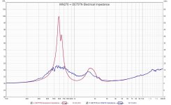
Pic2 : I tried the same electrical impedance test on a 5 x 285cm PWT. Unfortunately REW does not allow time gating during an impedance measurement. The raw curve (black) shows the lambda/4 nulls from an unterminated PWT into freespace with no gating (not useful). So an improvised "muffler" was attached to the PWT end get a better impedance termination and measurement (orange). The gated SPL measurement (green) is shown as a reference.
Pic3 : comparing the DE75TN attached to the WN270 and then the PWT. The loaded impedance curves show high correlation. There is some difference that I suspect is from my improvised muffler. However, both the PWT SPL curve which is a scaled throat velocity profile (constant load), and the loaded electrical impedance curve could be extracted from a PWT measurement and used in BEM sim to predict the raw horn output from a specific driver.
Attachments
That's definitely a possibility. The PWT is suppose to be a constant load (via constant area), and the horn may have more loading. There is also the possibility that my improvised PWT end termination "muffler" was less effective at lower freq than the horn. I'm not sure how to prove either hypothesis at this point, until I can make a more ideal PWT termination or REW supports gating for impedance measurements.
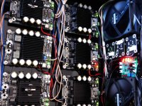
Some time ago, I removed the small (60mm) fans from all my amplifier boards and used 2 case fans (120mm) to make it quiet. The fans were controlled with an analog adjustable voltage but it was manual and fixed with no temp sensing.
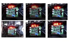
I found a low cost ($20) small 4 wire PWM fan controller with 2 temperature sensors that was also programmable. This also would allow me to see how hot the boards were running and automatically compensate. The control board was programmed for [35C-70C temp] -> [10%-100% DutyCycle] -> [400-1800rpm]. Unfortunately it does not have a discrete off state, so I'm forced to set a min fan speed to avoid a fan stall. The warmest heat sink is the woofer amp (8 drivers). The pic below show temp (top row) and fan speed/10 (bottom row) over the course of 45 min playing music at estimated 85-90dB.
I found a low cost ($20) small 4 wire PWM fan controller with 2 temperature sensors that was also programmable. This also would allow me to see how hot the boards were running and automatically compensate. The control board was programmed for [35C-70C temp] -> [10%-100% DutyCycle] -> [400-1800rpm]. Unfortunately it does not have a discrete off state, so I'm forced to set a min fan speed to avoid a fan stall. The warmest heat sink is the woofer amp (8 drivers). The pic below show temp (top row) and fan speed/10 (bottom row) over the course of 45 min playing music at estimated 85-90dB.
Attachments
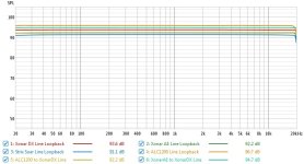
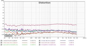
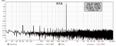
The motherboard for my audio PC failed and was replaced with another relic (circa 2008). It has a dual boot for Win10 and Mint. Occasionally I'll see a deal on older PC sound cards so I picked up another relic (XonarDX) and tested it against my current sound cards using the Linux side this time. I swap between the cards to see if I have a preference and to benchmark them. This measurement was done using REW in Linux Mint, with all sound cards installed, all cards controlled by the Pulse sound server (set to 32bit float, @48Khz) and ALSA uses 24bit @48Khz. ALSA card names and order were user configured.
These settings (24b@48Khz) were chosen after listening to TIDAL HiFi plus which has multiple audio quality selections for the same track (up to 24b, 192Khz). I can hear the difference between lossy compressed (320kbps AAC) and lossless (FLAC), and the difference between CD_16b and FLAC_24b, but no difference in sampling freq past 48Khz.
The StrixSoar and XonarDX use the same ADC (Cirrus Logic CS5361) which is typically the limiting factor on soundcard loopbacks, as the DACs are typically better. I usually use the StrixSoar (ESS DACs).
don@audio:~$ cat /proc/asound/cards
0 [Loopback ]: Loopback - Loopback
Loopback 1
1 [ALC1200 ]: HDA-Intel - HDA Intel
HDA Intel at 0xfcff8000 irq 26
2 [GT640 ]: HDA-Intel - HDA NVidia
HDA NVidia at 0xfe7fc000 irq 17
3 [XonarDX ]: AV200 - Xonar DX
Asus Virtuoso 100 at 0xe800, irq 18
4 [XonarAE ]: USB-Audio - XONAR SOUND CARD
ASUSTeK XONAR SOUND CARD at usb-0000:06:00.0-1, high speed
5 [StrixSoar ]: USB-Audio - STRIX SOUND CARD
ASUSTeK STRIX SOUND CARD at usb-0000:02:00.0-1, high speed
Attachments
- Home
- Loudspeakers
- Multi-Way
- Modular active 3 way - work in progress