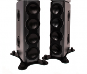
Proof of concept for my suggestion = Kii Audio BXT:
Interesting idea for more bass:
4 front plus 4 rear drivers all driven in phase
rear drivers just contribute below 100 Hz
resistive side vents on front drivers for cardioid
rear drivers make up for the bass lost through the side vents
Interesting idea for more bass:
4 front plus 4 rear drivers all driven in phase
rear drivers just contribute below 100 Hz
resistive side vents on front drivers for cardioid
rear drivers make up for the bass lost through the side vents
Attachments
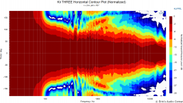
Yeah I suspect it all works just fine below the baffle width wavelength and minimizing diffraction making the side and front source radiation close like each other to all directions. Look at the Kii 3 top box, big roundovers, side woofers at the front edge, probably to get their outputs similar towards most directions. The bass tower is only 8" wide so perhaps problem free pattern up to say 1/2wl, to something like 500Hz.
Appreciate the discussion, I just want to re-center it.
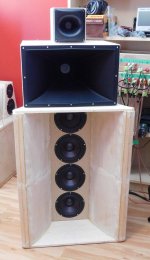
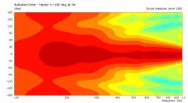
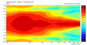
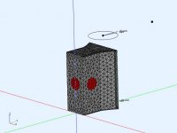
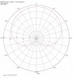
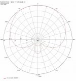
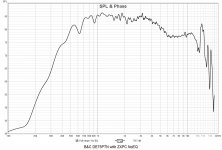
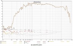
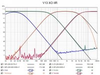
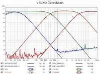
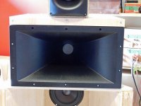
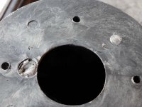
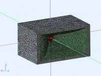
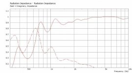
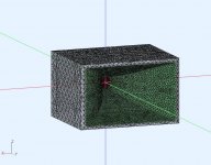
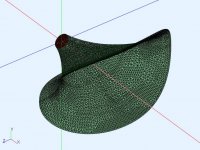
The bass horn is already built and has the desired characteristics above 300Hz (pic#1,2). It was designed to have a 60deg beam width at 700Hz to match a ZXPC horn. This is a high DI 3 way horn.
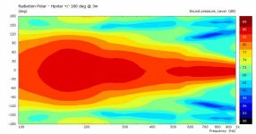
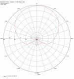
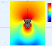
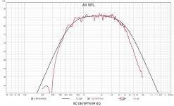
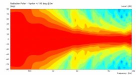
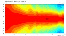
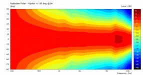
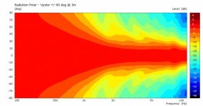
I was looking for ways to improve the response 100-300Hz by adding drivers at various locations to the existing bass horn. So far one driver on the back and one on each side seems to be working, but I'm always looking for better. The modifications (pic#3,4) indicate that I can get close to what I want, These adjunct drivers would be in small sealed boxes (if I built them) but would require DSP to implement.
[edit] - the simulations were done in AKABAK (3D BEM). Even though flat pistons are shown, there is a LEM (T/S parameters) model for each driver. The filters are also implemented in LEM with time delays to compensate for driver location. The horizontal polar results were taken at my midrange horn height and 3m distance.
The bass horn is already built and has the desired characteristics above 300Hz (pic#1,2). It was designed to have a 60deg beam width at 700Hz to match a ZXPC horn. This is a high DI 3 way horn.
I was looking for ways to improve the response 100-300Hz by adding drivers at various locations to the existing bass horn. So far one driver on the back and one on each side seems to be working, but I'm always looking for better. The modifications (pic#3,4) indicate that I can get close to what I want, These adjunct drivers would be in small sealed boxes (if I built them) but would require DSP to implement.
[edit] - the simulations were done in AKABAK (3D BEM). Even though flat pistons are shown, there is a LEM (T/S parameters) model for each driver. The filters are also implemented in LEM with time delays to compensate for driver location. The horizontal polar results were taken at my midrange horn height and 3m distance.
Attachments

Last edited:
Sorry for getting off track. Tmuikku made me do it. ") That and an excess of enthusiasm for the Kii 3.
That and an excess of enthusiasm for the Kii 3.
It looks like your side drivers have affected output on/near axis just above 400 Hz. I've seen that in my own sims. Steeper low pass filter on the side/rear drivers should fix that. There is a surprising amount of variability in response shape by tuning delay and drive strength. My best results were with a falling frequency response for the side drivers and a phase EQ PEQ at the limit of their range. Can you tweak these things without resolving the entire model?
That and an excess of enthusiasm for the Kii 3.It looks like your side drivers have affected output on/near axis just above 400 Hz. I've seen that in my own sims. Steeper low pass filter on the side/rear drivers should fix that. There is a surprising amount of variability in response shape by tuning delay and drive strength. My best results were with a falling frequency response for the side drivers and a phase EQ PEQ at the limit of their range. Can you tweak these things without resolving the entire model?
No problem.
The filters and time delays are in LEM (electrical), so no need to resolve BEM (no physical changes), just rerun the analysis (10sec).
The side drivers are rolled off at LP=260Hz (BW3) and rear control driver is rolled off at LP=200Hz (BW3). Time delay compensations is added to both. The front drivers are rolled off HP=60Hz (BW2). This seems to make everything coherent.
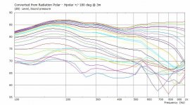
This is probably as good as I can make V14.5, with side and rear drivers using IIR filters. It would be easier in FIR to have more arbitrary phase control. At 100Hz there is -12dB rear attn and -5dB side attn, and a smoother transition from 100Hz to MF. An interesting exercise.
Front drivers : G=1. Td=0ms, HP-BW2-80Hz, LP (none in this model, actual 500Hz)
Side drivers : G=-0.8, Td=0.7ms, HP-BW2-30Hz, LP-BW3-250Hz
Rear driver : G=-1.0, Td=1.7ms, HP-BW2-40Hz, LP-BW3-190Hz
.
Front drivers : G=1. Td=0ms, HP-BW2-80Hz, LP (none in this model, actual 500Hz)
Side drivers : G=-0.8, Td=0.7ms, HP-BW2-30Hz, LP-BW3-250Hz
Rear driver : G=-1.0, Td=1.7ms, HP-BW2-40Hz, LP-BW3-190Hz
.
Attachments
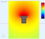
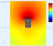
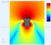
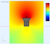
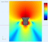
A few simulation observation fields [@100Hz, 210Hz, 304Hz] showing the SPL around the cabinet of V14.5 before and after. The field is 1m from the box edges (front, rear, side) to give me an indication of how much local space is required near field for this to work.
Pic #1,3,5 no control drivers (before)
Pic#2,4,6 with control drivers (after)
.
Pic #1,3,5 no control drivers (before)
Pic#2,4,6 with control drivers (after)
.
Attachments
-
 V14-5-HorzObsField-100Hz.jpg32.4 KB · Views: 73
 -
 V14-5-HorzObsField-ShapingDrivers-100Hz.jpg42.8 KB · Views: 66
 -
 V14-5-HorzObsField-210Hz.jpg37.1 KB · Views: 64
 -
 V14-5-HorzObsField-ShapingDrivers-210Hz.jpg41.6 KB · Views: 68
 -
 V14-5-HorzObsField-304Hz.jpg37.2 KB · Views: 68
 -
 V14-5-HorzObsField-ShapingDrivers-304Hz.jpg41.1 KB · Views: 70
Midrange driver change B&C DE75PTN
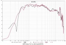
Trying to improve things, starting with changing the midrange driver from a D2200Ph (2"VC, Phenolic) to DE75PTN (3"VC, Titanium). Strangely, the actual B&C part is marked "TN", sold as "PTN", but there is no data sheet on the B&C site for just a "TN". It appears to have a metal phase plug. At some point I'll measure it on a PWT ( I need data for modelling anyways) and post the results. There is some discussion on this driver by @Ro808 at DE75xxx
These measurements were using a ZXPC horn (11x17x12). Not surprising, the B&C is the better driver, with lower THD, less ripple, better separation, and crisper sound. It could be used over maybe [500-12Khz] but I prefer [600-5KHz] LR4 in this 3way horn. The deviation from the template at >5Khz is from DSP IIR Biquad related frequency warping and not the driver. Comparing it to the D2200 which sounds warmer and actually does OK considering it's a much lower price point. However, the B&C is staying cause I'm happier with it.
.
Attachments
Suffix 'PTN' means plastic phase plug + Titanium diaphragm, like this:

Despite their age - the first DE75 was launched about 30 years ago, the DE72(TN), DE75(TN), DE75P(TN), DE82(TN), DE85(TN), DE700(TN) and DE750(TN) easily stand comparison with many modern drivers, as illustrated by your measurements.
Cymbals, metal strings etc. probably sound more natural / more lifelike compared to the PRV?
Last edited:
Hi Ro808,
It definitely sounds more life like (compared to D2200), like new strings. The parts I have are actually labelled DE75TN and it looks like they have a metallic phase plug with a little oxidation. I also see the DE75PTN data sheet also shows DE75TN part labelling. I'm OK with either I just wanted a driver with 3" titanium diaphragm that would reach 500Hz, to use as a midrange. I'll probably buy some aftermarket aluminum diaphragms to hear what they sound like as well.
It definitely sounds more life like (compared to D2200), like new strings. The parts I have are actually labelled DE75TN and it looks like they have a metallic phase plug with a little oxidation. I also see the DE75PTN data sheet also shows DE75TN part labelling. I'm OK with either I just wanted a driver with 3" titanium diaphragm that would reach 500Hz, to use as a midrange. I'll probably buy some aftermarket aluminum diaphragms to hear what they sound like as well.
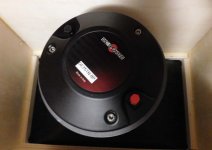
Sound card Xonar AE, S/W DSP
I wanted to integrate a few pieces of equipment for playback, testing, server and making configuration(s) changes a little easier.I have an old PC (MN2-SLI deluxe MB, Phenom9850, circa 2008) lying around and decided to repurpose it. Windows10 can be installed without a licence and it has an optional "compatibilty pkg" for older H/W that worked perfectly. I even installed the SoundMax Vista audio drivers for the on board soundcard. Then I added an ASUS Xonar AE Pci card, installed EqAPO, Rephase, REW, and Spotify. The PC has flexible fan control so it can be made fairly quiet as well. The PC (bare) is placed beside the amp to minimize ground loops, using short audio cables, and accessed via RDP. Time for s/w DSP.
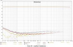
The Xonar has 3 different DACs, ESS ES9023 (headphones), Cirrus CS4245 (R,L), and Cirrus CS4361 (RR,RL,C,S,SR,SL). The A/D has a HP filter that can be disabled (datasheet) but there does not seem to be a windows control for it. Usually the input A/D is the weakest link in a loopback test. Sound wise I don't hear the difference between the min phase and linear phase but I'm still playing with it. It also sounds comparable to my active analog XO. The PC load is 12% total for 8 x 8K taps x 32bit FIR at 44.1KHz playing Spotify. The PC load is only 8% for the IIR filters.
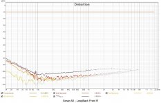
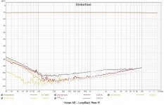
Pic#1 - loopback THD for ES9023
Pic#2 - loopback THD for CS4245
Pic#3 - loopback THD for CS4361
Pic#4 - Equalizer APO used to implement min phase IIR filter XO, and ideal templates
Pic#5 - Equalizer APO used to implement convolution FIR based linear phase filter XO, and ideal templates
Attachments
ZXPC 18x10 Horn
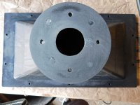
I bought a pair of the ZXPC 18x10 horns for comparison to the ZXPC 17x11 horn. The shorter 18x10 should not load as low, but it should have a wider beamwidth and it should radiate more acoustic power w.r.t the narrower 17x11. I'll post the AKABAK model results for this 18x10 horn and system spinorama prediction when I get time to finish it. Both horns have the same width, but the 18x10 actually has a smaller mouth area because the mouth flange is wider. I reused the same box with a vertical fill plate (pic#6).
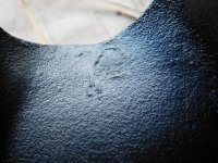
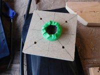
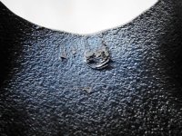
The ZXPC 18x10 has known quality issues (pic#1,2) and I've included pics of my adjustments (pics #3,4). The 18x10 walls and flange are thicker than the 17x11 but I still use a driver support to avoid stressing the plastic. The mounting surface has imperfections near the throat (inside and outside) that were filled with epoxy and sanded flat. The mounting holes required re-drilling (minor), and I used a quick centering jig (pic#3) to center and tweak the hole pattern.
Last (pic #7) is a comparison between the horns (no EQ), and both can load low enough for my application and the DE75TN.
Attachments
You previously expressed interest in Edgar midrange horns.
If the idea still interests you, you could use those ZXPC horns to build a variant. You might already have spare cone drivers that would suit. It doesn't take a lot of finess to try out - I just used thin foam to make gaskets, and gave a pile of different drivers a go.
A decent driver will give ~105dB from 400Hz up to 1.5 or 2kHz. A smaller driver, or EQ, can give more HF at the expense of some sensitivity. From graphs Freddy posted for the 2nd version (using a JBL 5"), it looks like 5kHz extension required about 10dB of EQ with that particular parts combination.
YMMV, but I seem to prefer cone mids, rather than CD mids. They are definitely a lot more robust
I still have interest in horns on cones/domes, I built a few midrange horns with small drivers and was never able to get the range I wanted (500Hz-5KHz) without excessive EQ. It was easier with a 2inch CD. It would be interesting to compare the two solutions. I think it would require a phase plug for the cone as well as the 2inch adapter if the ZXPC horns were used. Maybe easier to start from scratch.
Comparison, ZXPC models 18x10x8 vs 17x11x12
I was comparing these two horns to see if I had a preference for beamwidth (DI) and radiated power. The model 18x10x8 is approx 80x50deg (~1.23sr) and the 17x11x12 is approx 60x35deg (~0.65sr) so the 18 is radiating ~2x the acoustic power of the 17 when both are flat on axis. I actually prefer the 18 because it's power response is closer to my woofer horn and the speaker sounds more balanced (in a room). The tradeoff is slightly degraded imaging (wr.t 17), but its still more than good enough. The 18 does not load the driver as low as the 17, so a little more EQ required, but not really an issue as my XO's will probably remain LR4 in the 600Hz-5KHz region. I would actually prefer a larger horn mouth to better control the pattern to a lower freq, so maybe I can model the effect of extending the horn a little more. It will be interesting to see the effect on the speaker spinorama report (next).
A note on the horn models. The horns were measured (intercepts on ZX, ZY planes) to create the model, however getting a more accurate throat profile (first 3cm fillets) would require something like a 3D laser scanner. This small residual error might be causing some "ripples" in the model response, but it's still sufficient for it's purpose (anechoic beamwidth, loading).
Attachments
-
 ZXPC-18x10x8 RadImp.jpg28.9 KB · Views: 71
 -
 ZXPC-18x10x8 Vpolar.jpg24.1 KB · Views: 70
 -
 ZXPC-18x10x8 Hpolar.jpg26.5 KB · Views: 74
 -
 ZXPC-18x10x8 Model V1.jpg74.5 KB · Views: 70
 -
 ZXPC-17-11-12in-RadImp.jpg30.8 KB · Views: 78
 -
 ZXPC-17-11-12in-Vpolar.jpg22.6 KB · Views: 73
 -
 ZXPC-17-11-12in-Hpolar.jpg21.9 KB · Views: 79
 -
 ZXPC-17-11-12in-model.jpg90.4 KB · Views: 84
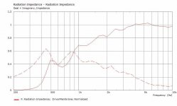
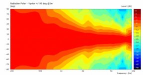
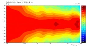
Custom Horn WN_SEL_425_A4 - Spherical Horns
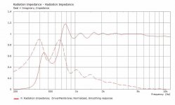
After listening to the 2 x ZXPC horns (18x10 and 17x11) I preferred some of the properties of each horn. There are not many production 2inch horns and most are custom or rare (expensive). So it's time to make my own.@docali (many thanks) (@ https://sphericalhorns.net/ ) generously provided his expertise and calculators to design and simulate 2 horns that are specific to my preferences for the 3 way horn system. The first (WN_SEL_425_A4), is a super ellipse, ~75x50deg coverage, with loading to 500Hz for a 2inch driver. Pics for the model, polars and radiation impedance are below. The second (WN_SEL_275_A5_M5) will be posted when I complete it.
Attachments
Last edited:
- Home
- Loudspeakers
- Multi-Way
- Modular active 3 way - work in progress