Variable inductance with frequency is something that occurs in all inductive loads, and without it, high inductance subwoofer simulations are very inaccurate. Woofer Tester Pro has a way of measuring variable Le, and simulating it is possible with their software. With that and with the help of @Bolserst, Hornresp now has the function of simulating it. Bolserst posted a spreadsheet on the Hornresp thread which can calculate semi-inductance/variable Le with frequency using impedance curves. With that, you can create much more accurate sims. Because of this, I will not simulate any speakers over 2mH of inductance without Semi-Inductance anymore. Here is a link to the spreadsheet: Hornresp - Page 851 - diyAudio
Here is a list of Semi-Inductance drivers:
Semi-Inductance Drivers - Google Drive
Here is a list of Semi-Inductance drivers:
Semi-Inductance Drivers - Google Drive
Attachments
-
Dayton DCS305-4 12 Semi-Inductance.txt247 bytes · Views: 128
-
B&C 12PLB100 measured semi inductance.txt249 bytes · Views: 101
-
B&C 12NDL88-16 semi-inductance.txt242 bytes · Views: 67
-
B&C 12NDL88-4 semi-inductance.txt240 bytes · Views: 57
-
B&C 12NDL88-8 semi-inductance.txt240 bytes · Views: 83
-
B&C 12TBX100-8 Semi-Inductance.txt244 bytes · Views: 72
-
B&C 12TBX100-4 Semi-Inductance.txt244 bytes · Views: 71
-
B&C 12BG76 Semi-Inductance.txt239 bytes · Views: 61
-
B&C 12BG100 Semi-Inductance.txt242 bytes · Views: 78
-
Dayton LS12-44 12 Semi-Inductance.txt246 bytes · Views: 84
Last edited:
Anyone who has impedance files in the formats in the link above of drivers not in this thread and can't use Microsoft excel, post them to me and I will calculate the Semi-Inductance.
Attachments
That FP 12RS550 file is wrong. Here is the correct one and the Dayton Ultimax 12". Dayton supplies .Zma's for all their drivers so anyone with Microsoft word can calculate those.
Attachments
The inductance stays the same, its the impedance that changes.Variable inductance with frequency is something that occurs in all inductive loads, and without it, high inductance subwoofer simulations are very inaccurate.
They both change with frequency. This spec would not be called "semi-INDUCTANCE" if it was simulating variable impedance.

The speaker has an inductor in it which cant change.
The inductance is decided by length of coil and how many turns it has.
However, what will change is the impedance due to combination of inductance, capacitance and resistance in the speaker.
Unless, it is a switched inductance speaker or has two coils which are being manipulated.
Last edited:
Iirc the voicecoil inductance in a dynamic loudspeaker is lossy because of the reluctance in the magnetic circuit. The result is that the impedance curve does not rise as you would expect for a pure inductance when you use the T/S model. The 'real' inductance looks like a network of resistors and smaller valued inductors.
Last edited:
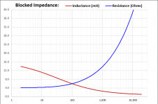
The following page may be of interest. It shows how to use the semi-inductance parameters in Hornresp, and gives an example of the effect it can have on the sim'd output of a simple sealed design.
The Subwoofer DIY Page - Semi-Inductance
The Subwoofer DIY Page - Semi-Inductance
VituixCAD has extended Z-model solver, iterating Le, Leb, Ke, Rss. Solver needs few T/S-parameters; Re, fs, Rms, Mms, VAS, Sd, BL and four f,Z-points which can be measured impedance response.
Simulated impedance (black) is quite accurate with extended parameters. Overlay in gold is Z-measurement in free air loaded for solver.
An externally hosted image should be here but it was not working when we last tested it.
Simulated impedance (black) is quite accurate with extended parameters. Overlay in gold is Z-measurement in free air loaded for solver.
An externally hosted image should be here but it was not working when we last tested it.
Inductance can change as a function of VC current or of excursion. Not really sure what the OP is really referring to though.The speaker has an inductor in it which cant change.
The inductance is decided by length of coil and how many turns it has.
However, what will change is the impedance due to combination of inductance, capacitance and resistance in the speaker.
Unless, it is a switched inductance speaker or has two coils which are being manipulated.
I could maybe see the inductance changing as a function of frequency as well, if the motor is designed with an inductance-reducing feature whose effectiveness varies with frequency. A rabbit hole, this is...
Anyone who has impedance files in the formats in the link above of drivers not in this thread and can't use Microsoft excel, post them to me and I will calculate the Semi-Inductance.
I'm trying to use the semi inductance model with this 18TBW100-8. Measured with DATS V2 after cooling down from 1 hr high-excursion break-in. Having trouble with the spreadsheet, could you add it to the list?
Attachments
The speaker has an inductor in it which cant change.
The inductance is decided by length of coil and how many turns it has.
Your second statement is correct as a baseline. your first is incorrect.
Inductance by definition, is the relationship between the current flowing through the system and the energy that is stored within the system by magnetic field.
The relationship is E = 1/2 L I squared.
A simple coil inductor like a typical crossover coil, will start to drop it's inductance as the frequency goes up. This is because the current will move inward within the wires due to proximity effect. Since it cannot cross the insulation, it will only go towards a limit, ten maybe 15% downdepending on wire section.
A coil near a metal object, the object will create eddy currents within, and those currents will produce a magnetic field which will in effect exclude the field of the coil. So the inductance goes down as the conductor approaches the coil, the eddies are dependent on rate of change of field, or frequency.
In a voice coil, many issues attack the inductance. Location within the gap, eddy currents in the pole and face plate and shorting rings, magnitude of the flux, as permeability goes down as the iron heads into saturation.
Even the velocity of the energized coil attacks inductance.
John
- Home
- Loudspeakers
- Multi-Way
- Thread for Drivers with Semi Inductance