Hi Zvu,
I have uploaded my data files. The Z offset is -33mm and Y offset -185mm for the woofer.
Cheers
Jason
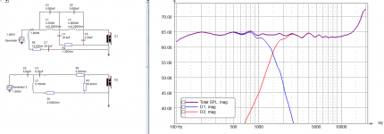
At a price of few components more, i'd do this:
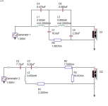
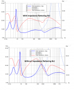
Crossover frequency is lower and stands at 1460Hz so power response should be smoother. It's a full baffle step design but with good positioning should yield better results.
Not all values can be found but you could make them. C2 for example, 5.6uF+2.2uF in parallel etc. You get the picture.
Lowest impedance is 6ohms and you could throw in an impedance flattening RLC.
Last edited:
Measuring distance is 1m i guess ?
Sorry, forgot that important piece of information. Measuring distance is 910mm. I adjusted the time window to account for that mic distance.
Love your work Zvu

That’s an awesome crossover design Zvu. Just means I’ll have to purchase all of the components as I don’t have any of those values in my stash.
My design is as good as are the files you provided. If they are right, it'll measure and sound good and you can tweak it per your taste.
That being said, i'm still a bit worried about the frequency response over 10KHz - not because you hear it or don't but because your tweeter shouldn't measure that way. I'm counting it off as a measurement artifact.
As for components, i've bought a lot of 3-4 hundred of 1uF/100V Philips MKC for about 20 euros and i have few Icar Ecofill Motor-run capacitors of various values ranging from 10uF to 100uF. I make the values that a need for testing purposes. When i'm sure it measures and sounds good, then i order permanent capacitors. Same for resistors. I have about 40x1ohm, 10x2.2ohm, 10x3.3ohm, 10x10ohm, 10x22ohm. The cheap 5W ceramic resistors - with that i can make any value i need. Coils i bought, some was given to me and i borrow some from friends, diy enthusiasts. I usually make mock up crossover of everything i model in simulator to compare to simulated response and to give it a listen before i go and buy it.
Last edited:
I've done this by entering 14mm offset but id does seem unlikely that acoustic center of woofer is in front of tweeter.
I made with -14mm offset for woofer as well so take your pick
View attachment 713952
Just out of curiosity, what’s the DCR of the 1mh and 0.7mh coils, or doesn’t it matter as long as the series resistances + coil resistances = crossover values supplied.
Cheers
It doesn't matter as long as sum resistance is the same or as similar as possible to resistor on the schematic. I recently ordered Jantzen coil of 3mH/Rdc 3 ohm and i added 1 ohm resistor per schematic. It is quite convenient because they are cheap and small so it is much easier to orient them properly on the crossover board - and the crossover doesn't weigh few kilos. That can be very important if you are pursuing flat frequency response and impedance. Series coils on midwoofer and woofer are important to be low Rdc to preserve as much of sensitivity as they can down low, but for midrange that is going to be attenuated or tweeter coil that has resistor with that coil in series, the smaller the better for me.
Last edited:
Slowly, slowly.
From the LspCAD 6 manual (http://www.ijdata.com/LspCAD%206%20manual.pdf, page 6):
From the LspCAD 6 manual (http://www.ijdata.com/LspCAD%206%20manual.pdf, page 6):
Note that a positive dz is away from the listener.
Back when i used PCD7 (forerunner of WinPCD) there was a catch about Z offset (positive value is closer to the listener).
Since Jason uses WinPCD i have no clue if it should be positive or negative value. That's why i offered both options so he can check in his simulator to see when will he get the same result.
When he does, that's the right offset.
Last edited:
Hi,
The Z value in WinPCD is negative for further away from listener. The tweeter is set to zero for x,y, and z, as I'm measuring on axis with the tweeter. Woofer y coordinate is -185mm, and z coordinate is -14mm, so below tweeter and further away.
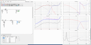
I tried plugging the crossover into winPCD, but because of the parallel bypass caps on the coils, it's hard to implement. I have to create a 4th order crossover, delete the coil values and then add 2 x series LC circuits. I think it works out, because when I create the crossover in X-Sim, the response looks similar.
The Z offset is quite tricky to get correct and very different to implement depending on the software used. I have WinPCD, Virtuix CAD, and X-Sim, and they can all give different results for the same data input. So which one should I believe?
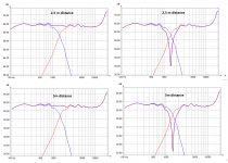
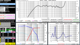
Using crossover from post 81. i get the same results with PCD7 and LspCAD6.
Here is comparison:
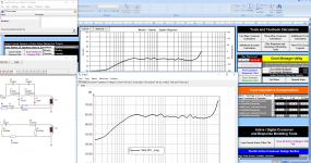
As you can see, offsets are good and i attached an explanation for Z offsets in PCD7. In PCD7 i had to enter -14mm because it takes the tweeter as a reference point and woofer's acoustic center is behind the tweeter. In LspCAD i entered +14mm because it takes microphone as a reference point so you have to add the distance in regard to mic. In both tweeter is X,Y,Z - 0 offset.
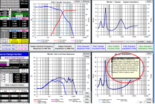
Here's the tweeter.
I really don't know why are you getting different results but it could have something to do with simulated listening distance or Z offset.
Here is comparison:

As you can see, offsets are good and i attached an explanation for Z offsets in PCD7. In PCD7 i had to enter -14mm because it takes the tweeter as a reference point and woofer's acoustic center is behind the tweeter. In LspCAD i entered +14mm because it takes microphone as a reference point so you have to add the distance in regard to mic. In both tweeter is X,Y,Z - 0 offset.


Here's the tweeter.

I really don't know why are you getting different results but it could have something to do with simulated listening distance or Z offset.
Last edited:
Finished
Hi all.
Here's my final crossover design for this project. It's a combination of Zvu's crossover and my own, using components I had in my parts bins.
The off axis response is really good and power response is excellent. I've checked and confirmed this in Win PCD. Everything matches in both software packages. It was the determination of Z offset in Virtuix CAD where I came unstuck.
I have been listening to them now for a few days and I like the way they sound. Slightly subdued but detailed at the same time. Female vocals shine. Bass is fantastic (I've turned my 12" subwoofer off).
Thanks to all who have helped and commented. I was close but not quite there until Zvu chimed in.
This is a great forum and look forward to doing more DIY projects in the future.
Cheers. Jason
Attachments
Last edited:
You are re-extracting minimum phase after applying all your FRD modifications (baffle step and / or baffle diffraction) aren't you?
I'm using actual data obtained via calibrated ECM8000 mic and associated hardware. Using REW to extract frd files with minimum phase data.
My technique was explained quite a few posts back. Is there a problem with the way I have done things?
Nothing was mentioned previously?????
- Status
- This old topic is closed. If you want to reopen this topic, contact a moderator using the "Report Post" button.
- Home
- Loudspeakers
- Multi-Way
- 2 way TL using SB23NBACS45 and SB29RDCN
