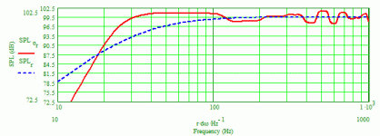
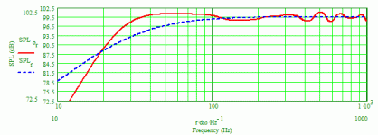
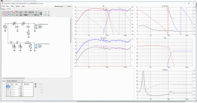
I modeled your 8:1 tapered TL using your T/S measurements, first with a stuffing density of 0.3 lb/ft3 (5 kg/m3), then 0.5 lb/ft3 (8 kg/m3) and have attached the two predicted anechoic system bass response curves (red lines). As always in speaker system design there are compromises, like trade offs between f3 and response smoothness.
Paul
Paul
Thanks Paul.
The line overall length is 1.9m. Sd1=800cm2 and Sd2=100cm2. The driver is located 30cm from the closed end. The filling is in the first 1.4m of the line at a density of 5kg/m3. Now that I know this level of fill is considered “light”, I’ll have another go with a density of 8kg/m3 to see the effect.
Cheers
Jason
Attachments
The Re=6.5ohm Wavecor TW030WA12 is a 30mm dome tweeter in a modest depth waveguide which both extends the low frequency range and provides controlled directivity. Looks like another option for your 2-way design.
TW030WA11 and TW030WA12 are tweeters designed for the most demanding applications, where low resonance frequency, high sensitivity and power handling, controlled dispersion, and a very wide frequency range are required.
FEATURES
• Featuring waveguide face plate for controlled dispersion, offering optimized off-axis and power response
• 30 mm voice coil design with high power handling, and low resonance frequency
• Copper clad center pole yielding very low voice coil inductance for reduced distortion and increased high frequency output
• Internal volumes for low resonance frequency and distortion
• Precision-coated textile diaphragm for improved consistency and high-frequency extension
• Optimized dome shape for ultra high frequency cutoff
• Vented voice coil former for reduced distortion and compression
• Copper-clad aluminium voice coil wire offering lower moving mass for improved efficiency and transient response
• Build-in cavities under dome/edge to equalize pressure for lower distortion and lower resonance frequency
• Flexible lead wires for higher power handling and larger excursion
• Gold plated terminals to prevent oxidation and ensure long-term reliable connection
• Delivered with foam gasket attached for hassle-free mounting and secure cabinet sealing
Looks like a good tweeter, but 115mm diameter is much bigger than the 72mm SB29RDCN. I'd like the drivers centre to centre as small as possible. Currently 155mm, would blow out with a larger diameter faceplate, and I'd have to re-design everything. But that's the fun of DIY, right.
I modeled your 8:1 tapered TL using your T/S measurements, first with a stuffing density of 0.3 lb/ft3 (5 kg/m3), then 0.5 lb/ft3 (8 kg/m3) and have attached the two predicted anechoic system bass response curves (red lines). As always in speaker system design there are compromises, like trade offs between f3 and response smoothness.
Paul
I get it now. 4db ripple is fairly substantial in the 200 - 500hz range and we need to smooth it as much as possible without sacrificing the bottom end response.
I'll have another go with a 10:1 taper and 10kg/m3 fill and play with the driver location to see if it can be tweaked some more.
The other thing now is the design of the box. TL mouth at top of box or bottom? Design was based on the 8" driver at the top of the box and tweeter directly below with 100mm offset from centre.
Jason
Paul,
You're absolutely right with the 10:1 taper. It's the best all round compromise between extension and ripple removal. I've settled on a 1.8m length, 10:1 with Sd1=1000cm2 and Sd2=100cm2, driver at 26cm from closed end, 8kg/m3 fill in the first 120cm.
Another question about TL mouth placement, is it ideal to have the mouth far away from the driver or does it not matter?
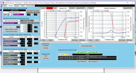
At first glance it appears both versions do a lot more to protect the tweeter down low. It would be informative to see how close these match to actual LR4/6/8 curves. Does VirtuixCAD have that capability? I'm used to Passive Crossover Designer (PCD) where you can pick a crossover type & slope as a target and design the crossover so the driver response matches that target.
Other than that it's down to measurements (on-axis, distortion, off axis, etc.) and listening to the drivers.
I've just modelled the data into Win PCD and the woofer roll off is bang on LR6, while the tweeter is almost LR8. So should have pretty good protection.
Attachments
Last edited:
I was planning on suggesting you increase the taper to 10:1 by simply increasing the beginning area to 1000 cm2, but you beat me to it. I assume when you say "TL mouth" you're referring to the line's exit, the terminus? I've never worried about the relative locations of driver and terminus. With line lengths of 5 feet or more, the line usually ends up being folded in half in its simplest form, and that results in the terminus being on the back panel, pretty far away from the driver. But, you can come up with a 2-fold, 3-segment line that would place the terminus on the baffle at the bottom. BTW, your modeling naturally assumes the line is continuous without any folds or corners, and if you do fold it, you need to model how the line's area actually changes going around the corners if you want a more accurate prediction of the performance. I don't know if the LA software allows folded lines to be modeled accurately, if at all.
Paul
Paul
Paul,
You're absolutely right with the 10:1 taper. It's the best all round compromise between extension and ripple removal. I've settled on a 1.8m length, 10:1 with Sd1=1000cm2 and Sd2=100cm2, driver at 26cm from closed end, 8kg/m3 fill in the first 120cm.
Another question about TL mouth placement, is it ideal to have the mouth far away from the driver or does it not matter?
The output won't be lowered but there will be minor unwanted effects, most of which can be neutered by the physical arrangement of the angled line divider. Let's say you have a line 70" long and you fold it once, creating two halves, each nominally 35" long. Let's also say the line started out with a depth of 10" and ended with a depth of 1" for a 10:1 taper. So, the internal dimensions of the enclosure needed will be about 35"H x 11-3/4"D (and let's assume a line width of 10"), assuming the divider is 3/4" thick. With the woofer located towards the top of the enclosure in the front half of the line, most often the bottom of the divider would be located such that it equally splits the enclosure's depth at its bottom, meaning the front of the divider at the bottom and the back of the divider at the bottom are both 5.5" from the baffle and back, respectively (and the bottom of the divider is 5.5" above the bottom of the enclosure). What you end up with is a straight, non-tapered length of the line across the bottom of the cabinet which shortens the effective length of the line. To mostly mitigate this, you would instead locate the bottom of the divider so its front edge is more than 5.5" behind the baffle (6" let's say), its bottom is 5.5" above the internal bottom of the enclosure, and its back edge is less than 5.5" in front of the back panel (5" let's say). Last your modeling would then have short 3 straight short sections each with a smaller area than the previous section and more like a tapered line. Overall the line would start with area dimensions of 10"W x 10"D and end at 10"W x 1"D, with three short non-tapered sections in the middle of the line that stepped down the area from 10"W x 6"D to 10"W x 5.5"H to 10"W x 5"D. It's a lot easier to understand this with a drawing. Just for a reference, one can pretty much create the response of a continuously and smoothly tapered line by using multiple (at least 5 but more is better) constant area sections, each of which has a smaller area than the previous section.
Paul
Paul
Paul,
I haven’t really looked into that side of the program, but on first looks, I don’t think it can model a folded line. Will the folds cause more ripple or lower the output?
Last edited:
With regard to driver centre to centre spacing, what would be the furtherest spacing possible without messing up imaging and crossover response?
Currently the C2C spacing is 155mm with a crossover point of 1250Hz. I could even make it 150mm by shaving a little off the tweeter frame.
I'm asking because that wavecor tweeter does look really good, and available in Australia, but distance increases to 175mm at least.
Cheers.
Currently the C2C spacing is 155mm with a crossover point of 1250Hz. I could even make it 150mm by shaving a little off the tweeter frame.
I'm asking because that wavecor tweeter does look really good, and available in Australia, but distance increases to 175mm at least.
Cheers.
Last edited:
The output won't be lowered but there will be minor unwanted effects, most of which can be neutered by the physical arrangement of the angled line divider. Let's say you have a line 70" long and you fold it once, creating two halves, each nominally 35" long. Let's also say the line started out with a depth of 10" and ended with a depth of 1" for a 10:1 taper. So, the internal dimensions of the enclosure needed will be about 35"H x 11-3/4"D (and let's assume a line width of 10"), assuming the divider is 3/4" thick. With the woofer located towards the top of the enclosure in the front half of the line, most often the bottom of the divider would be located such that it equally splits the enclosure's depth at its bottom, meaning the front of the divider at the bottom and the back of the divider at the bottom are both 5.5" from the baffle and back, respectively (and the bottom of the divider is 5.5" above the bottom of the enclosure). What you end up with is a straight, non-tapered length of the line across the bottom of the cabinet which shortens the effective length of the line. To mostly mitigate this, you would instead locate the bottom of the divider so its front edge is more than 5.5" behind the baffle (6" let's say), its bottom is 5.5" above the internal bottom of the enclosure, and its back edge is less than 5.5" in front of the back panel (5" let's say). Last your modeling would then have short 3 straight short sections each with a smaller area than the previous section and more like a tapered line. Overall the line would start with area dimensions of 10"W x 10"D and end at 10"W x 1"D, with three short non-tapered sections in the middle of the line that stepped down the area from 10"W x 6"D to 10"W x 5.5"H to 10"W x 5"D. It's a lot easier to understand this with a drawing. Just for a reference, one can pretty much create the response of a continuously and smoothly tapered line by using multiple (at least 5 but more is better) constant area sections, each of which has a smaller area than the previous section.
Paul
Thanks Paul.
I have done a couple of TL subwoofers in the past and I used some 6mm ply and lots of liquid nails to create the curves around the folded sections. I started with blocks at 45 degrees to the corners and then moulded the ply around.
Cheers
Jason
Looks like a good tweeter, but 115mm diameter is much bigger than the 72mm SB29RDCN. I'd like the drivers centre to centre as small as possible. Currently 155mm, would blow out with a larger diameter faceplate, and I'd have to re-design everything. But that's the fun of DIY, right.
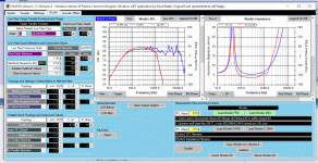
Here's the response with the wavecor tweeter. Crossover is approx. 1250Hz.
It looks good as well.
Attachments
Those values seem odd to me. Where are these measurements from? Wavecor: homepage?
SB: traced?
Have you incorporated baffle diffraction/baffle step and phase?
Otherwise nice project idea
The original response was traced from hificompass test and then baffle diffraction added, and then incorporated into the crossover.
Last edited:
And, you wasted lots of time and effort because the pretty curves you added around the corners are completely useless as far as making the performance better is concerned. The stuffing in the line absorbs all of the unwanted higher frequencies and the wavelengths of the low frequencies l are so long that reflectors in the corners aren't even "visible", plus all they do is consume volume in the line. There's absolutely nothing wrong with having right angles in the corners of line folds; just make sure you model the area properly going around the corners, then make sure you build what you modeled. But if it makes you feel better, using pretty curves/reflectors in the corners won't hurt the performance very much.
Paul
Paul
Thanks Paul.
I have done a couple of TL subwoofers in the past and I used some 6mm ply and lots of liquid nails to create the curves around the folded sections. I started with blocks at 45 degrees to the corners and then moulded the ply around.
Cheers
Jason
Hi All.
Now that the enclosure is sorted out (many thanks to Paul), I need some help deciding on a tweeter for this project. My initial design was with the sb29rndc, but the wavecor tw030wa12 has simulated just as well. My concerns are driver spacing and how this will affect the crossover and overall sound (lobing, beaming etc). Can someone shed some light on this?
Now that the enclosure is sorted out (many thanks to Paul), I need some help deciding on a tweeter for this project. My initial design was with the sb29rndc, but the wavecor tw030wa12 has simulated just as well. My concerns are driver spacing and how this will affect the crossover and overall sound (lobing, beaming etc). Can someone shed some light on this?
So, I have been messing about with the crossover software and have determined that the SB29rdcn tweeter is the better match to the SB woofer. The bonus is they are cheaper than the wavecor tweeters, and the component list is a little cheaper due to smaller valued caps. I’m now sourcing my mdf to make the box and will update when I have some actual response data on the baffle.
Cheers.
Cheers.
Hi all.
Now I’m in another conundrum. Where to locate the tweeter.
The baffle is going to be 300x900mm with the woofer centre located 290mm from the closed end of the line. That leaves just enough room to locate the tweeter at the top of the baffle with a 75mm horizontal offset.
Will the tweeter location be too high? Should I locate the tweeter below the woofer?
Cheers.
Tweeters can go pretty much where you want, being sealed back. Inverted designs have nothing wrong with them, particularly if it gets the tweeter at listening height. But this is usually done to get the lobing in BW3 designs where you want it.
I must say this is all fascinating to watch. It would never occur to me to even attempt a two way with such a wildly unsuitable driver:
SB Acoustics :: 8" SB23NBACS45-8
I speak as someone who likes 8" bass plus tweeter, and has built a lot of them. But always with well-behaved drivers.
This sort of thing has been done before:
TRYM
Maybe it's OK, maybe it's horrible. IDK. The SEAS driver is easier, IMO.
I think you should leave yourself an escape route if this all crashes and burns. Leave room for a midrange enclosure somewhere that might make this a three way as akarma 76 implied.
SBAcoustics-3WC
The bass modelling is really the least of your problems here, IMO.
Steve,
I’m still a newbie, but have built the Sb 3 way classic, have a mini monitor 2way with sb15nrx and vifa d25ag, and a 2.5 way with 4 x sb15nrx and sb29rdcn. This wasn’t ever going to be easy, but I’d like to have a good crack at it. Being a TL, doesn’t leave me much room for a mid box anyway. My woofer data at present is full of diffraction artifacts due to my measurement location, so it’s not as bad as it looks. I’m going to mock up a new baffle with sides and measure again in a better location. To my ear, a 1.1 - 1.2k crossover point is the sweet spot. My roll off is 8th order acoustic with my latest simulation version.
Cheers.
- Status
- This old topic is closed. If you want to reopen this topic, contact a moderator using the "Report Post" button.
- Home
- Loudspeakers
- Multi-Way
- 2 way TL using SB23NBACS45 and SB29RDCN
