Hi,
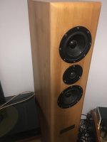
I have custom speakers with morel mdt33 - tweeter and eton 5-880 25 Hex mid/bass.
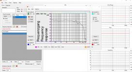
Frequency Response:
mdt33: 1800 - 20000 Hz
5-880/25 Hex: 50-4000 Hz
Lately I’m trying to build my own crossover, because I’m not satisfied with the current. I’ve never done something like that before, so I started learning by myself.
I’ve watched videos and read tutorials that explains how to do that.
So this is the result, I would be happy to hear what you think.
Did I make it right?
I have custom speakers with morel mdt33 - tweeter and eton 5-880 25 Hex mid/bass.
Frequency Response:
mdt33: 1800 - 20000 Hz
5-880/25 Hex: 50-4000 Hz
An externally hosted image should be here but it was not working when we last tested it.
Lately I’m trying to build my own crossover, because I’m not satisfied with the current. I’ve never done something like that before, so I started learning by myself.
I’ve watched videos and read tutorials that explains how to do that.
So this is the result, I would be happy to hear what you think.
An externally hosted image should be here but it was not working when we last tested it.
Did I make it right?
Attachments
I see you are on moderator approval, so the first 5 posts take a while... ")
But welcome to the forum.
I think it's good to find a similar project and try and replicate it:
Vifa PL14WJ-
What you are doing so far is impedance correction and maybe online calculator values for L and C on the bass. That doesn't include bafflestep, so the speakers will sound bass light. Phase looks a bit strange. Usually a 5" has acoustic centre about 30mm back, a 1" tweeter about 15mm back. Simulators need to know this.
It can be done with some skill:
Seas ER18RNX with 27TDFC
A 5" bass is usually crossed above 3kHz, because its dispersion is good up to that point.
The masterpiece of 5" bass is the BBC LS3/5A. Many good ideas in that one. Fairly adaptable to a lot of 5" basses. the parallel LCR on the bass is a very useful notch around 1kHz.
I should mention that to convert a single woofer circuit to twin parallel, you halve inductance and resistance and double capacitance on the bass circuit. Then adjust tweeter level for more output. Knowing that, you can then convert ANY similar MT project to MTM. Cool, eh?
Attachments
Last edited:
Did I make it right?
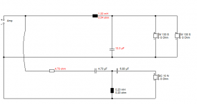
No no no. Tweeter is almost okay. Filter for mid-woofers is totally wrong. It's very close to short-cut with impedance of 1 Ohms. First coil (0.1m) should be much bigger, maybe 0.68-0.82mH. First shunt cap (68u) is usually 15-27uF with 4 Ohms load. Remove next shunt R+L (1+0.47m) and second shunt cap (56u). Then start again; tune component values, invert polarity and increase HP order if necessary and so on.
Wow, thanks!
I made your Instructions
what you think?
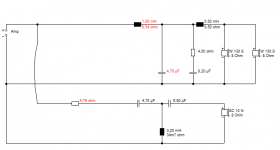
I made your Instructions
what you think?
An externally hosted image should be here but it was not working when we last tested it.
Attachments
Last edited:
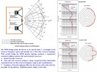
hubi, look over the MTM polar pattern diagram attached to understand polar pattern vs. crossover.
Your current crossover looks like LR2-tweeter circuit and LR2-midwoofers circuit, which typically generates one center-directed lobe(see diagram) - often favored for seated HT because it reduces reflections off of close walls.
Based upon your listening environment, using a BW3-tweeter circuit and BW3-midwoofers circuit will generate a much wider vertical lobe to fill the room with 180-degree polar reflections- sometimes favored for increased room ambience - Big Symphony.
Using a BW3-tweeter circuit and LR2-midwoofers circuit offers some phase shift improvements for a flat baffle, plus a wide polar pattern. The TM Starling xover is BW3-tweeter + LR2-midwoofer_with baffle step comp.. which will generate a wide polar pattern with 6"-7" driver MTM.(see diagram)
Attachments
what you think?
Not good
If mid-woofers are also for bass (not just midrange) you better remove external series resistance (3.3ohms) and leave only DCR of the coil, and start over. Sorry.And while reading BW3 etc philosophies about lobing, remember that you should not ruin power response for that kind of (or any) reason. Make such compromise which has also good power & DI. But you need complete set of off-axis responses to simulate power & DI - as you can see from my sample projects (Kontiainen & Epe-3W).
Last edited:
Oh dear, all this stuff about MTM lobing...
You get what you get with drivers. Sometimes it's all phase aligned, sometimes it goes 90 degrees and butterworth. This one tends to phase aligned on a simple circuit. And nothing wrong with that.
Just like the Troels project:
Vifa PL14WJ-
Here's a couple of circuits to try. About 3.5kHz crossover. Complicated and simple. Both should sound OK. I could make either of those more butterworth and 90 degree phase by increasing the sharpness of the filters, but it is not easy for a beginner to grasp that sort of stuff. And I'm not sure it matters much. It is slightly different from Troels' idea, because he is using a 3 ohm tweeter. You have a 6 ohm one, so LC values change in the tweeter crossover. Caps smaller, coils bigger when you raise impedance. Just how it works.
Happy modelling.
Attachments
Last edited:
When you do an SPL trace, you need to know what conditions the bass measurement was done. And inform the simulator.
Most hobbyists measure in the actual used enclosure. Manufacturers don't. SEAS use some standard boxes close to typical use.
What I am getting at is that bass response you are getting looks close to +6dB wall-mounted or infinite baffle measurement. Shouldn't be that high in the bass once it's in a box.
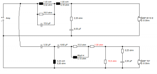
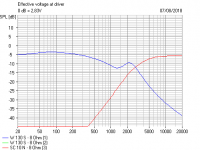
Below is yet another way to do the bass filter. This one ends up quite butterworth and 90 degrees at 4kHz crossover, which may suit an MTM. The LCR notch is a moveable feast that suits some drivers. Here it works at 1.3kHz. You take out the resistance to see where it acts on FR.
The Zobel and 22R resistor in the tweeter section is just one of those "sounds good" ideas. It damps the tweeter voicecoil, so might sound smoother.
Most hobbyists measure in the actual used enclosure. Manufacturers don't. SEAS use some standard boxes close to typical use.
What I am getting at is that bass response you are getting looks close to +6dB wall-mounted or infinite baffle measurement. Shouldn't be that high in the bass once it's in a box.
Below is yet another way to do the bass filter. This one ends up quite butterworth and 90 degrees at 4kHz crossover, which may suit an MTM. The LCR notch is a moveable feast that suits some drivers. Here it works at 1.3kHz. You take out the resistance to see where it acts on FR.
The Zobel and 22R resistor in the tweeter section is just one of those "sounds good" ideas. It damps the tweeter voicecoil, so might sound smoother.
Attachments
This paper has math + illustrations which explain how multiple driver T+M and M+T+M topologies interact to generate the polar dispersion. Think of the speaker cone as a collection of points generating air pressure waves. Around the crossover frequency when all cones vibrate at the same frequency, several different points separated by several inches can generate air pressure waves which reach the listen's ear at different angles which might combine in phase and raise the SPL, or null out-of-phase to reduce the SPL.Sorry it's too much for me - I did not get it ...
Biro Technology
Vertically Symmetric Two-Way Loudspeaker Arrays Reconsidered
MITHAT F. KONAR, AES Member
Biro Technology
With the tool inside -> VirtuixCAD - SPL Trace
That alone is usually wrong method, but it may work if manufacturer has measured driver in a cabinet which is close (size and shape) of your box. For example Seas measures in a box, but most of the manufacturers measure to half space i.e. driver is flush mounted in the wall or very large baffle.
Proper method and gear to produce measurement data at home (without large anechoic lab) is here, but very shortly:
Preparation of response measurements for crossover simulation with VituixCAD
And againg, name of the program is VituixCAD (without R)
Small addition. You can load traced half space response to VituixCAD Diffraction tool and generate axial response to full space. That is usually minimum effort with traced responses to get decent estimation about baffle step. Diffraction tool is also able to generate directivity; off-axis response in two planes to +/-180 deg, but that is quite reliable only with woofer of 3-way because cone is simulated as ideal piston.
Thanks to everyone
I'm getting crazy, I tried some new xovers but the original one that i don't love - sounds best of all of my tries.
I decided to make modifications to the original one.
The problem with him is that I hear to much mid when there is a bass tone.
Any suggestions how I can fix that?
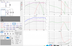
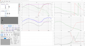
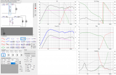
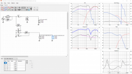
I draw in the original one in VituixCAD 2 (sorry for R from before)
I'm getting crazy, I tried some new xovers but the original one that i don't love - sounds best of all of my tries.
I decided to make modifications to the original one.
The problem with him is that I hear to much mid when there is a bass tone.
Any suggestions how I can fix that?
I draw in the original one in VituixCAD 2 (sorry for R from before)
Attachments
Last edited:
I'm struggling to read this but it looks like L2 in the tweeter filter is 0.82mH.

Lots wrong with it. If a diyaudio member had designed it, I'd say it was complete rubbish and he/she would go off in a huff. But it is rubbish. Shame it isn't a diyaudio member.
* Tweeter phase is wrong. This is positive polarity.
* The way the tweeter filter is wired after the RL bafflestep adjust is just stupid. It should be wired on its own circuit with a 2.4R attenuator.
* Using a purely reactive fourth order bass with no impedance correction or resistors makes for that huge midrange bump at 1.3kHz.
* Crossover is unnecessarily low.
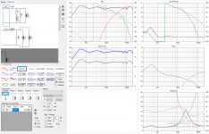
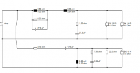
I knocked something better up using a lot of your components, but it looks like that bump at 1.3kHz needs attention. I think I suggested a notch circuit:

That looks most promising to me. You could try 4.7uF/0.3mH/6.8uF in the tweeter circuit too. 0.6mH and 15uF in the bass LC would probably be OK too..
Lots wrong with it. If a diyaudio member had designed it, I'd say it was complete rubbish and he/she would go off in a huff. But it is rubbish. Shame it isn't a diyaudio member.
* Tweeter phase is wrong. This is positive polarity.
* The way the tweeter filter is wired after the RL bafflestep adjust is just stupid. It should be wired on its own circuit with a 2.4R attenuator.
* Using a purely reactive fourth order bass with no impedance correction or resistors makes for that huge midrange bump at 1.3kHz.
* Crossover is unnecessarily low.
I knocked something better up using a lot of your components, but it looks like that bump at 1.3kHz needs attention. I think I suggested a notch circuit:
That looks most promising to me. You could try 4.7uF/0.3mH/6.8uF in the tweeter circuit too. 0.6mH and 15uF in the bass LC would probably be OK too..
- Status
- This old topic is closed. If you want to reopen this topic, contact a moderator using the "Report Post" button.
- Home
- Loudspeakers
- Multi-Way
- Crossover advice