Has anyone tried or simulated the Seas W22EX in a transmission line?
From running the numbers thru the alignment tables in my old copy of Loudspeaker Design Cookbook I believe the element to be suited, however I believe there are more accurate modelling tools available.
I am contemplating a makeover of my old Seas Trym speakers from reflex to TL so I guess baffle width is fixed. http://seas.no/images/stories/diykits/pdfdataheet/trym_cab.pdf
Assuming Seas' published T/S values for this driver are reasonably representative, I think it would work pretty well in TL, either tapered or mass-loaded (ML-TL). A 10:1 tapered TL would need a line length of 70-80 inches in order for its 1/4-wavelength resonant frequency to optimally tune the system for this driver; but it might be necessary to use a shorter line with a larger taper ratio to achieve optimum results. Any tapered line that would work well could be converted to an ML-TL of the same length and volume with equal or slightly better performance in specific areas.
Paul
Paul
Has anyone tried or simulated the Seas W22EX in a transmission line?
From running the numbers thru the alignment tables in my old copy of Loudspeaker Design Cookbook I believe the element to be suited, however I believe there are more accurate modelling tools available.
I am contemplating a makeover of my old Seas Trym speakers from reflex to TL so I guess baffle width is fixed. http://seas.no/images/stories/diykits/pdfdataheet/trym_cab.pdf
I tried a MLTL using Martin King's Mathcad worksheets. I made these assumptions:
- Use the original width, depth and material dimensions. This gives an internal width and depth of 9” and 11.5” respectively.
- The spacing of the drivers remains the same including the distance of the tweeter from the top. This also fixes the distance of the woofer from the top, one of the MLTL variables.
- The tweeter height will be 35” from floor; this fixes the internal height to about 38” (37.9”).
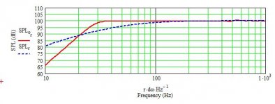
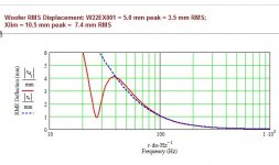
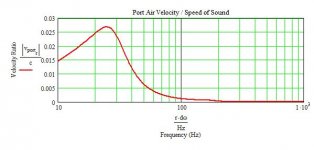
With those assumptions the gross volume would be 64 L and I subtracted 0.5L for the speaker and bracing. I ended up with 0.5 lb/ft3 stuffing density in the top 24". The port, 3” diameter and 8” long, is placed 5” above the internal bottom.
Here’s what I got with a 18 W input signal (anechoic response, no room or boundary effects) for SPL, excursion and port velocity. Note that the excursion is RMS, not peak or peak to peak.
- Use the original width, depth and material dimensions. This gives an internal width and depth of 9” and 11.5” respectively.
- The spacing of the drivers remains the same including the distance of the tweeter from the top. This also fixes the distance of the woofer from the top, one of the MLTL variables.
- The tweeter height will be 35” from floor; this fixes the internal height to about 38” (37.9”).
With those assumptions the gross volume would be 64 L and I subtracted 0.5L for the speaker and bracing. I ended up with 0.5 lb/ft3 stuffing density in the top 24". The port, 3” diameter and 8” long, is placed 5” above the internal bottom.
Here’s what I got with a 18 W input signal (anechoic response, no room or boundary effects) for SPL, excursion and port velocity. Note that the excursion is RMS, not peak or peak to peak.
Attachments
I used Martin King's software "ML-TL Corner", and I can model tapered TLs or ML-TLs with it quickly. If tapered and folded, though, Martin's "Sections" software is necessary to correctly model the line around the fold.
Paul
Paul
Thanks, so with the smaler line I'm looking at an internal volume of approximately 60 liters.
What software tool is it that you are using for the modelling?
I used Martin King's software "ML-TL Corner
I tried download from quarter-wave.com only it is blocked by username and password. Any idea how I can go about contacting Mr. King for purchasing a license?
Are there any sonic differences to the conventional TL and the ported MLTL solutions as proposed by ernperkins?
Very near the top of the home page for Quarter-Wave there's a link to Martin's Yahoo group primarily devoted to TLs. If you become a member of that group you can get access to Martin's software.
For truly equivalent tapered and mass-loaded TLs, there will be no sonic differences. Each has their pros and cons; with the same line volumes, the ML-TL will have a bit lower f3, whereas the tapered TL will have a much lower air velocity in its terminus than in the port of the ML-TL. Also, the overall response of the ML-TL will be usually be smoother above 300 Hz so than that of the tapered TL.
The ML-TL that ernperkins modeled is the simplest form of an ML-TL. The internal height of the cabinet is the line's length and while its 1/4-wavelength resonant frequency contributes some to the overall system tuning, most of the tuning comes from the port acting on the line's volume. There's nothing at all wrong with that design and I've built several similar designs, but I prefer a longer line where its 1/4-wave resonance plays a bigger part in the tuning.
Paul
I tried download from quarter-wave.com only it is blocked by username and password. Any idea how I can go about contacting Mr. King for purchasing a license?
Are there any sonic differences to the conventional TL and the ported MLTL solutions as proposed by ernperkins?
So, I went shopping wood for the new cabinets today.
Since this is also a case study before my next set of DIY speakers, I decided to go with the conventional line.
For my next project MLTL is an option due to cabinet shape.
It should be noted that I have decided to deviate somewhat from the original Trym layout. I believe the Trym is an early design and I will eventually attempt an XO redesign. This change of layout has the effect of putting the bass element in a slightly different location compared to pkitt's modelling. I don't think this is as critical for a conventional TL as it is for an MLTL?
Before I start cutting I hope someone verify my understanding of pkitt's modelling.
Attached images show two alternative boxes. I believe box #1 should be very close that proposed by pkitt. Alternative #2 has a slightly longer line, but if necessary, I can shorten it further by lifting the start of the line by making a false bottom.
So my questions before I make final decition towards alternative 1 or 2 are:
- How critical is the line lengths
- How important is the radius fillets, and what do you propose to make them from?
- Do the start of the line have to be level, or is it OK if it is slanted (I.e - do I have to make the cavity for the XO in alternative#2 or is it OK to simply attach the XO to the cabinet at the start of the line?
- Any other comment you may have
Attachments

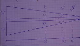
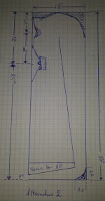
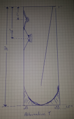
The driver location in the line is important but if it's within an inch of that modeled, negative effects will be very minor. If you want the performance that I modeled, you need to build it as I modeled, however. Those fillets around the corners are absolutely useless regarding the line's performance. They are the result of old and incorrect theories and all they do is consume some of the line volume. The line's beginning doesn't have to be exactly horizontal but the beginning of the line's length is measured from the middle of that angled member. You can definitely locate the crossover as shown; however, the crossover, the woofer and any braces you add, all consume volume which will affect the bass reach a bit. In order to compensate for consumed volumes, estimate their total amount and calculate what percentage that is of the total line volume, then simply increase the internal (and line) width of the cabinet by the same percentage when you build (the volume for the angled line divider is automatically compensated for in the modeling). For sketch 2, there will be reinforcement from the floor boundary of the terminus' output, which may be "too much of a good thing". You won't have that problem with that shown in sketch 1.
Paul
Paul
So, I went shopping wood for the new cabinets today.
Since this is also a case study before my next set of DIY speakers, I decided to go with the conventional line.
For my next project MLTL is an option due to cabinet shape.
It should be noted that I have decided to deviate somewhat from the original Trym layout. I believe the Trym is an early design and I will eventually attempt an XO redesign. This change of layout has the effect of putting the bass element in a slightly different location compared to pkitt's modelling. I don't think this is as critical for a conventional TL as it is for an MLTL?
Before I start cutting I hope someone verify my understanding of pkitt's modelling.
Attached images show two alternative boxes. I believe box #1 should be very close that proposed by pkitt. Alternative #2 has a slightly longer line, but if necessary, I can shorten it further by lifting the start of the line by making a false bottom.
So my questions before I make final decition towards alternative 1 or 2 are:
- How critical is the line lengths
- How important is the radius fillets, and what do you propose to make them from?
- Do the start of the line have to be level, or is it OK if it is slanted (I.e - do I have to make the cavity for the XO in alternative#2 or is it OK to simply attach the XO to the cabinet at the start of the line?
- Any other comment you may have
I think that cries out for an explanation or just what are the old and the new theories?...They are the result of old and incorrect theories...
BTW, here's my theory:
Long pipe to sequester rear wave
B.
The incorrect theory (probably more accurately called guesses) about using deflectors or fillets in the corners was that those "steered" the sound wave more smoothly around them, but that's not true. The stuffing in a line is an acoustical, low-pass filter, so only the long wavelengths get through, and those wavelength are so long that they don't even "see" the deflectors or fillets.
Paul
Paul
I think that cries out for an explanation or just what are the old and the new theories?
BTW, here's my theory:
Long pipe to sequester rear wave
B.
and... at low frequencies approaching the line's quarterwave resonance it acts like a solid slug of air moving within the line. This is because @ resonace the wave becomes planar. If we do not smooth the corners then the exact same turbulance that occurs in air ducts booger up the smooth flow required to maximized bass output cleanly.
As the old adage goes, there is no replacement for displacement. In a TL to maximize bass output you must maximize flow. Anything below 30hz requires flow, ask Bruce Thigpin.
As the old adage goes, there is no replacement for displacement. In a TL to maximize bass output you must maximize flow. Anything below 30hz requires flow, ask Bruce Thigpin.
So the general question is how to handle the wrap with respect to the reflection, the hole, and the placement of damping too. While textbook-like precision always appeals to members of this forum, it is heterogeneity and un-tuning that I think works better to avoid having any characteristic "voice" to your sub. You would make an irregular hole and leave the turn square for that goal.
B.
B.
Slow progress
For a variety of reasons things are moving ahead slower than what I'd hoped for. I am planning to close the boxes later today. Before I do that I would like your advice on stuffing.
At the moment I have bitumen on every panel, and some lining on top and bottom of the cabinet, hoping to kill of some standing wave modes.
For stuffing I intend to use long fibre wool from my old Bailys, simply because that is what I have at hand right now.
I have four questions.
- Lining: Should I put more lining than what I already have (see picture)?
- Is recommended amount of line stuffing the same for polyester as for wool (0.75 lb/cu.ft. for the first 2/3 of the line).
- In terms of midrange quality, am I better of with a little less filer behind the mid-woofer or should I keep fill density constant
- Later, when doing impedance sweeps, what should I look for in terms of determining amount of stuffing? Will near-field SPL close to the line terminus be a better measure?
Attachments
At the moment I have bitumen on every panel, and some lining on top and bottom of the cabinet, hoping to kill of some standing wave modes.
biteminum will do nothing to affect standing waves. It is intended to damp panel resonances (but can often backfire).
Is recommended amount of line stuffing the same for polyester as for wool (0.75 lb/cu.ft. for the first 2/3 of the line).
There will be a difference, even between different species of polyfluff. Wool is good for damping but not for stability and is a good moth food. i would mix with some poly to get stability with most of the dampin gof the poly.
dave
If we do not smooth the corners then the exact same turbulance that occurs in air ducts booger up the smooth flow required to maximized bass output cleanly.
For the very reasons stated, the turbulence does not affect the LF only stuff up higher, the expansion at teh corner acts as an additional LP so one can use a (tiny) buit less damping with a corresponding increase in bass (ie less suppresion of the fundemental from the damping)
dave
Following the topic. I realized a TL with w22 in a 3 way with seas w15cy: the intersection between wf and mid it’s a damning mess...it’s caused by the ripple due to the room and the TL. Maybe in a 2 way this could be avoided (the xo point in my system is 400hz) i don’t know. Or maybe that was due to my wrong approach. Anyway i’m waiting for your result.
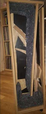
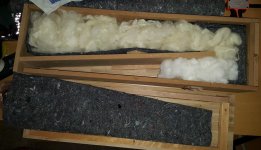
Still moving ahead at snail pace. As can be seen in the attached image, at least now the woodwork for the first cabinet is close to done. Some pigmented wax is on order for the finishing.
I guess I was not quite clear. I have mass loaded the cabinet with Bitumen, Then lined the walls in the first part of the line with 10mm lining. First half of divider (closer to woofer) and side walls lined, baffle is un-treated.
Top and bottom of cabinet has double lining.
Due to the lining I decided to start of with 0.5 lb/cu.ft. of stuffing for about 2/3 of the line length. If I were to re-do the stuffing I think I would have increased the amount slightly as I felt it was difficult to fluff it sufficiently to fill the full volume and to maintain an even density.
Following the idea of Planet-10's proposal and using what I had at hand I stuffed the line part of the line closest to the terminus with poly fill and the remaining part of the line with wool as per attached picture.
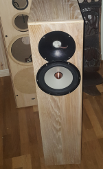
What remains now is to make a dummy plate to put in place of the waveguide so that I can actually start testing the T-line. All things going well, I hope to be able to post impedance plots and near-field SPL plots for woofer and line plots upcoming weekend.
An a different topic: Has anyone tested the or seen test results for the Seas Millenium tweeter in waveguide?
biteminum will do nothing to affect standing waves. It is intended to damp panel resonances (but can often backfire).
dave
I guess I was not quite clear. I have mass loaded the cabinet with Bitumen, Then lined the walls in the first part of the line with 10mm lining. First half of divider (closer to woofer) and side walls lined, baffle is un-treated.
Top and bottom of cabinet has double lining.
Due to the lining I decided to start of with 0.5 lb/cu.ft. of stuffing for about 2/3 of the line length. If I were to re-do the stuffing I think I would have increased the amount slightly as I felt it was difficult to fluff it sufficiently to fill the full volume and to maintain an even density.
There will be a difference, even between different species of polyfluff. Wool is good for damping but not for stability and is a good moth food. i would mix with some poly to get stability with most of the damping of the poly.
dave
Following the idea of Planet-10's proposal and using what I had at hand I stuffed the line part of the line closest to the terminus with poly fill and the remaining part of the line with wool as per attached picture.
What remains now is to make a dummy plate to put in place of the waveguide so that I can actually start testing the T-line. All things going well, I hope to be able to post impedance plots and near-field SPL plots for woofer and line plots upcoming weekend.
An a different topic: Has anyone tested the or seen test results for the Seas Millenium tweeter in waveguide?
Attachments
- Status
- This old topic is closed. If you want to reopen this topic, contact a moderator using the "Report Post" button.
- Home
- Loudspeakers
- Multi-Way
- Seas W22XL in Transmission Line