Hi all,
I am new to diyAudio and would like to start building my first project. I have completed re-planning my speaker, but I would like someone to look it over. I know that I will make mistakes, and I am not afraid to scrap everything and restart.
I re-started from scratch from my first plan, here is the old thread:
First project
Thanks all")
Edit: I know I need two L-Pads. Ignore that
I am new to diyAudio and would like to start building my first project. I have completed re-planning my speaker, but I would like someone to look it over. I know that I will make mistakes, and I am not afraid to scrap everything and restart.
I re-started from scratch from my first plan, here is the old thread:
First project
Thanks all
Edit: I know I need two L-Pads. Ignore that
Attachments
Last edited:
I think there is something you still don't understand about the lpads, and I'm sure no one is going to ignore it
The resistor before the woofer may be changing the response, but it is not a good idea, and unnecessarily wastes power.
Have you factored in the baffle response? I assume you are using factory curves at this stage. The effect of the baffle will have a big impact on the low frequency drivers response curve
Tony.
I agree with both the above points.
Since you are using vituixcad, simulate the full space baffle response and use it as the frequency response for the woofer. you may find that you do not need that resistor in series to the Woofer.
If you are planning to use a series resistor on the woofer, it means the project has started out on the wrong foot.
Have a look at the sticky thread about designing xo's without measurement.
I think there is something you still don't understand about the lpads, and I'm sure no one is going to ignore it
The resistor before the woofer may be changing the response, but it is not a good idea, and unnecessarily wastes power.
Have you factored in the baffle response? I assume you are using factory curves at this stage. The effect of the baffle will have a big impact on the low frequency drivers response curve
Tony.
Save yourself a whole lot of time and grief and just buy a full range speaker.
Fane 12-250TC or Fane 15-300TC.
I love mine especially the 15.
An externally hosted image should be here but it was not working when we last tested it.
I think I fixed the crossover. Is it better now?
Attachments
An externally hosted image should be here but it was not working when we last tested it.
I think I fixed the crossover. Is it better now?
The Cone breakup will be audible with this one. and considering that its an aluminum cone. it may ring badly. Woofer should be crossed over early.
Go back to the Crossover in the first post. Remove all resistors and reduce the woofer inductor to 1mh. You will get the flat response you are looking for.
However, in reality the output will differ as there will baffle step diffraction taking place.
Here is how you calculate baffle step in Vituixcad. Tools-> diffreaction
1.provide the box width and height you plan to use.
2.input the sd value from spec sheet.
3.input the woofer FRD file as the halfspace response file.
4.click the checkbox for fullspace respose and "export" the output.
The exported output should be used as the woofer FRD when designing the crossover.
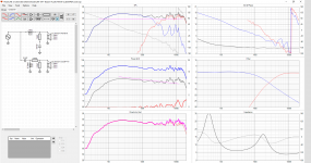
I followed those steps and changed the low pass to second order. (or at least I think I did) Is this good now?
Attachments
I followed those steps and changed the low pass to second order. (or at least I think I did) Is this good now?
Tweeter has to be crossed atleast an octave above Fs. ie: crossover point needs to be at 2k or above.
You dont need to compensate for baffle step for complete 6db. Just compensate 3-4 db, the rest will be compensated by reflections and room gain.
Tweeter has to be crossed atleast an octave above Fs. ie: crossover point needs to be at 2k or above.
You dont need to compensate for baffle step for complete 6db. Just compensate 3-4 db, the rest will be compensated by reflections and room gain.
Is this better? I hope the woofer isn't audible at those higher frequencies. Other than that am I done?
(probably not) I hope the L-pad will deal with the baffle stuffAttachments
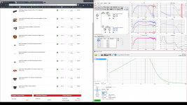
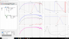
In post #10 the Q of the filters is too high (peaking up near the crossover frequency), leading to too much output in the upper midrange and lower treble. This will make them sound very shouty. The impedance also dips very low in the treble. The 0.12mH inductor is probably a culprit for both problems - it needs to be made larger.
The design in post #8 looks much better, I would go back to working on that one. Moving the crossover up to about 2KHz is a safer best to avoid distortion from the tweeter at high volumes. Your phase tracking is also not ideal - note that there is 45degrees separation between the woofer and tweeter near the crossover frequency. Try to get that closer to 0degrees. You should be able to accomplish this by moving the tweeter crossover up while leaving the woofer alone. If you get a slight dip in the overall response at the crossover frequency (which should now be about 2kHz), play with the Q of the filters to fill it in.
The design in post #8 looks much better, I would go back to working on that one. Moving the crossover up to about 2KHz is a safer best to avoid distortion from the tweeter at high volumes. Your phase tracking is also not ideal - note that there is 45degrees separation between the woofer and tweeter near the crossover frequency. Try to get that closer to 0degrees. You should be able to accomplish this by moving the tweeter crossover up while leaving the woofer alone. If you get a slight dip in the overall response at the crossover frequency (which should now be about 2kHz), play with the Q of the filters to fill it in.
Last edited:
In post #10 the Q of the filters is too high (peaking up near the crossover frequency), leading to too much output in the upper midrange and lower treble. This will make them sound very shouty. The impedance also dips very low in the treble. The 0.12mH inductor is probably a culprit for both problems - it needs to be made larger.
The design in post #8 looks much better, I would go back to working on that one. Moving the crossover up to about 2KHz is a safer best to avoid distortion from the tweeter at high volumes. Your phase tracking is also not ideal - note that there is 45degrees separation between the woofer and tweeter near the crossover frequency. Try to get that closer to 0degrees. You should be able to accomplish this by moving the tweeter crossover up while leaving the woofer alone. If you get a slight dip in the overall response at the crossover frequency (which should now be about 2kHz), play with the Q of the filters to fill it in.
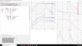
Try a 3rd order filter.
Will reduce the tweeter excitation at Fs and rolls off the woofer very quickly so the breakup is not audible.
Using a third order crossover worked a lot better, and got rid of the spikes at the xover frequency. I also was able to get the phase to nearly match
Attachments
Tweeter has to be crossed atleast an octave above Fs. ie: crossover point needs to be at 2k or above.
You dont need to compensate for baffle step for complete 6db. Just compensate 3-4 db, the rest will be compensated by reflections and room gain.
How would I only compensate 3-4db in vituixcad?
I think there is something you still don't understand about the lpads, and I'm sure no one is going to ignore it
The resistor before the woofer may be changing the response, but it is not a good idea, and unnecessarily wastes power.
Have you factored in the baffle response? I assume you are using factory curves at this stage. The effect of the baffle will have a big impact on the low frequency drivers response curve
Tony.
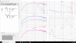
I factored in the baffle response and removed the resistor. How's it now?
How would I only compensate 3-4db in vituixcad?
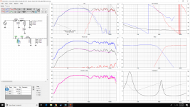
When you do the baffle step simulation the resulting FRD, should peak somewhere near 1K. Adjust your inductor/cap combo for the woofer so that the peak is 3-4 db down. Then adjust your Tweeter level to match.
When you do the baffle step simulation the resulting FRD, should peak somewhere near 1K. Adjust your inductor/cap combo for the woofer so that the peak is 3-4 db down. Then adjust your Tweeter level to match.
Like this?
Attachments
I factored in the baffle response and removed the resistor. How's it now?
Yes you have come quite a way in a fairly quick time

- Status
- This old topic is closed. If you want to reopen this topic, contact a moderator using the "Report Post" button.
- Home
- Loudspeakers
- Multi-Way
- First project (revised)