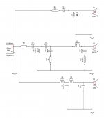
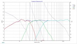
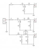
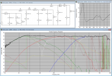
Ok, Here's a 2.5 way XO, I used SBA NRX as a sub, I know it is a woofer with a wide FR but why not it is an exercise, the Mid is Volt 228.8 and Tweeter is 9130 with LR2.
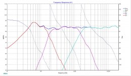
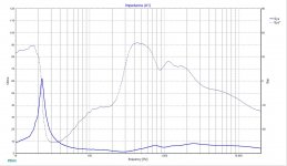
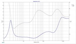
Tried to hit Steen Duelund target curves as system7 suggested, so any improvements since last time or any suggestions ? how the impedance curve look ? I m abit concern about very mild dip between 1k and 2k, I know I can work around it tho.
The purple is higher than the blue means your are out of phase through the mid passband = destructive.
I'm a bit concerned about the low freq impedance. I've nevervseen a resistor in parallel with a shunt cap. Not sure how that will affect the two shunt caps in paralell. But I'll assume they are effectively around the 50uf mark.
What's the impedace curve like without them?
Tony.
I went through so many XOs I do not remember where did I picked that up. it did changed the the impedance curve tho.
The purple is higher than the blue means your are out of phase through the mid passband = destructive.
thanks, I over looked it.
any better ?
Attachments
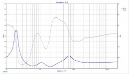
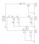
Go 2nd order electrical on the bass filter to raise impedance. The 300uF cap will be lowering impedance a lot. You want to get that down to 150uF or less. Drop the 5mH inductor and lower the 10mH to raise xo Freq and provide a lower order slope. You'll need to watch phase integration more closely and alter the highpass on the mid as a result.
How much baffle step comp are you factoring?
How much baffle step comp are you factoring?
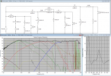
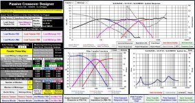
As an example - here's a 3 way I'm currently working on. This is using actual measurements (to factor in baffle diffraction / ripple) but I had to splice in the frequency response below the gated measurement and account for baffle step with a near field measurement. I used Jeff Bagby's excellent spreadsheet tools. These do apply a 1/48th octave smoothing to the response curves. I then extracted minimum phase then entered driver offset (Z) into the crossover simulation. It might give you food for thought.
Note the series notches (in parallel) with drivers are there to tame metal cone breakups and may not be required or require different values for fabric / softer dome/cone materials.
The rule of thumb with drivers that have breakups (FR peaks) at the top of their operating range is to ensure you can either:
a) measure yourself
b) use someone elses measurements but ENSURE the drivers are consistent with the manufacturer.
Note the healthy impedance minimum (4.4 ohms) in the higher current midbass area. This was achieved with 2nd order slopes. I could not get 4th order with higher impedance. The cost here is more excursion from the midrange.
Attachments
+1 I completely missed that!C5 with L5 generate this low impedance.
The bass filter contribute only a little.....
Tony.
how about now ?
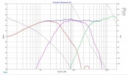
Did some changes, impedance looks better now. still worry about mid respond tho, what do you think ?
I also tried 2nd order and couldn't pull it off, this NRX doesn't behave.
and no baffle step at this moment, I know i know, but i m taking baby steps and haven't touch baffle step territory yet
Did some changes, impedance looks better now. still worry about mid respond tho, what do you think ?
I also tried 2nd order and couldn't pull it off, this NRX doesn't behave.
and no baffle step at this moment, I know i know, but i m taking baby steps and haven't touch baffle step territory yet
Attachments
Last edited:
The SB23 looks flat to 1Khz according to manufacturer specs. Your scan speak has only 2.3mm xmax so I wouldn't push it any lower than 500Hz with a 2nd order acoustic target.
HEre's what I would do
Push the W-M crossover point higher. The SB23 can do this. Say 500 - 600Hz. Try 2nd order slopes. I would still recommend modeling the scan excursion at the bottom end here to make sure it can handle it.
Push the M-T higher as well. Say 3Khz. The scan off axis is still very good there
So - W-M - 500 - 600 Hz and M-T ~ 3KHz.
Also will mean smaller value inductors (= cheaper build).
When designing a speaker - you may want a certain XO point, but the drivers may naturally *gel* with different points. It's about being flexible and shifting slope and frequency, trying asymmetric on one side etc... until you something that aligns (impedance, FR, excursion etc...)
The SB23 looks flat to 1Khz according to manufacturer specs. Your scan speak has only 2.3mm xmax so I wouldn't push it any lower than 500Hz with a 2nd order acoustic target.
HEre's what I would do
Push the W-M crossover point higher. The SB23 can do this. Say 500 - 600Hz. Try 2nd order slopes. I would still recommend modeling the scan excursion at the bottom end here to make sure it can handle it.
Push the M-T higher as well. Say 3Khz. The scan off axis is still very good there
So - W-M - 500 - 600 Hz and M-T ~ 3KHz.
Also will mean smaller value inductors (= cheaper build).
When designing a speaker - you may want a certain XO point, but the drivers may naturally *gel* with different points. It's about being flexible and shifting slope and frequency, trying asymmetric on one side etc... until you something that aligns (impedance, FR, excursion etc...)
I m hoping to design a 2.5way of my own, and I used the NRX as a sub, I know it can be crossed much higher but I just used it here since I had the FRD/ZMA file ready that s why I crossed it so low, and that's why it does not behave I think
the mid is a Volt BM165 not a scan speak, recommended freq is 50 to 3000 bt a look at the curves it shows that it start breaking down around 3000Hz so I brought it down to around 1500-2000Hz, and since the Fs on BM165 is 30Hz it should be fine to be crossed around 150hz not s easy to tame tho since it it supposed to be used in a 2 way.
any how I traced Volt B2549 Sub now ( all the drivers I m planing to buy) and re did the crossover w same mid and tweeter, sub is crossed at 250-300Hz. this is the first try, didn't even have time to redo it but check it out (not sure if I sure be happy w impedance curve).
Attachments
Last edited:
One more...
haha, I m not actually gonna invest into it until I get things right and i m not in a hurry, just a goal for now, anyhow I m not going to bore you with sending a crossover after another one, I will comeback when I have better understanding, one question tho, I used Jeff Bagby Crossover Design sheet this time, all 2nd order LR, at 250Hz and 2000Hz, with mentioned drivers, in JB XO sheet if I introduce 3cm z offset between tweeter and woofer (acoustic offset) and reverse the tweeter I can get rid of dip caused by the offset and get a flatish FR (work in progress) but when I simulate it in xsim, everything looks good until I add 3cm to tweeter, reversing the polarity in xsim does not behave as it does in JB XO Sheet. am I missing something here ?
sorry bout all noob Qs.
Attachments
Going with the impedance under 4 ohm will destroy your amplifier.
Decrease C5 value and increase L5 value (L5>=8mH).
Increase L3 value and decrease C3 value.
Play with the values on these components until you get the desired shape but taking care to the impedance to be over 4ohm.
Decrease C5 value and increase L5 value (L5>=8mH).
Increase L3 value and decrease C3 value.
Play with the values on these components until you get the desired shape but taking care to the impedance to be over 4ohm.
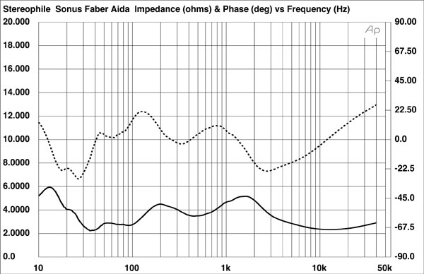
haha thanks, I will start looking for Impedance/Price Tag ratio curve thenLow impedance seems to be allowed, if the speaker is expensive enough, in six-digit class!
.
Here's my 3 way "so far". it's taken a while to get to this point. You have to be persistent.
I find 2nd order acoustic W-M provides higher impedance. I gave up on 4th order here regarding impedance. It was easier to make 2nd order work with phase tracking then 4th order impedance.
very interesting, this helps a lot, thanks.
- Status
- This old topic is closed. If you want to reopen this topic, contact a moderator using the "Report Post" button.
- Home
- Loudspeakers
- Multi-Way
- Crossover exercise !