Wondering if you guys could look over what i have thus far and advise me. Is this okay is it wrong, would you do something different?
Looking for LCR F40(50max) as loce to 90 dbs as i can, i want something i can play at reference and not have them commit suicide.
This is my first Build from scratch- I was just going to copy the Volt-10V2 but cant figure out all xover parts and order haha and id probably feel like a tool. yea i know you can buy the kit but id rather just order it all my self and build it and make my own cabs...
Attachments
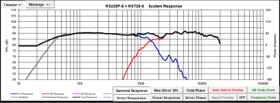
Try a smaller vertical scale to better see what is happening. Crossover calculators do not work, you have to manually tune the values. Could you draw a schematic of your circuit? You might want to suppress the woofer cone breakup at 3 and 4 kHz as it currently only is 20 dB down, which you can hear as a metallic sound. You could also lift the tweeters top end to counter the 5 dB droop.
It's OK to borrow information from a speaker with similar drivers, like Dayton Reference RS225
It's OK to borrow information from a speaker with similar drivers, like Dayton Reference RS225
Hi, this program is about the only way I can learn. O tried others and they won't even load driver haha- I'm a hands on guy, with three kiddos umder 5 I need all the help I can get. Thank you for the link- it helps a lot. I'll do what I can to clean that up- the link k provided actually clears some confusion up, o thought I had way too much stuff going on here in my attempt. This is bagbys passive crossover and has a page for schematics which is nice I just match corresponding part on it. This is my first crossover build and from scratch speaker build so my knowledge is miniscule
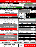
The tweeter could be flatter and attenuated a touch more. Try a little more series resistance. Try it in front of the xo too and see if there's any difference.
Your C9 and C10 values are very large (and expensive). Try lowering them.
Turn on the "Driver Phase". You want to align the driver phase as best you can in the region of the xo. Minimum phase should have already been extracted from both the FR and Z files.
You also need to add the resistance values of your inductors.
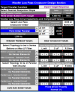
If you are working with the paper version, breakup won't be as bad as the metal version but lowering it may still be a good idea. You could try an LCR or you may be able to do it with a simple tanking capacitor in parallel with the 1st woofer inductor. That takes a little creativity to set up in PCD though. You set L2 to 0, keeping the correct series R in place beside it and then below, select an LCR before the xo and set L to your L2 value (1.8mH ), C to whatever works (maybe start around 1uF and go up or down from there) and then R to something huge like 999999 which the program reads as not being there.
Make sure you are working with the program's target transfer functions. LR4 acoustic are probably best for this design.
Never hurts to see what your x, y and z set-up values are too.
And given that the RS225P-8's sensitivity is 89dB, I'm wondering if you have added in the necessary baffle diffraction for both the woofer and the tweeter? System sensitivity should end up closer to about 84dB after the usual 6dB of baffle step loss.
Finally, measuring your in-box FR, Z responses and acoustic centers and then working with PCD or similar is the best way to go. Using sims alone may be accurate but usually they tend to end up just a little bit off for various reasons.
Your C9 and C10 values are very large (and expensive). Try lowering them.
Turn on the "Driver Phase". You want to align the driver phase as best you can in the region of the xo. Minimum phase should have already been extracted from both the FR and Z files.
You also need to add the resistance values of your inductors.
If you are working with the paper version, breakup won't be as bad as the metal version but lowering it may still be a good idea. You could try an LCR or you may be able to do it with a simple tanking capacitor in parallel with the 1st woofer inductor. That takes a little creativity to set up in PCD though. You set L2 to 0, keeping the correct series R in place beside it and then below, select an LCR before the xo and set L to your L2 value (1.8mH ), C to whatever works (maybe start around 1uF and go up or down from there) and then R to something huge like 999999 which the program reads as not being there.
Make sure you are working with the program's target transfer functions. LR4 acoustic are probably best for this design.
Never hurts to see what your x, y and z set-up values are too.
And given that the RS225P-8's sensitivity is 89dB, I'm wondering if you have added in the necessary baffle diffraction for both the woofer and the tweeter? System sensitivity should end up closer to about 84dB after the usual 6dB of baffle step loss.
Finally, measuring your in-box FR, Z responses and acoustic centers and then working with PCD or similar is the best way to go. Using sims alone may be accurate but usually they tend to end up just a little bit off for various reasons.
HI- Well im pretty sure i didnt add anything correctly, I picked two drivers loaded them into the program and started trying XO values to get it as flat as i can. I have the tweeter inverted as normal polarity made it nuts.
Not sure what you mean"Try it in front of the xo"- im still learning the program, i will try your recommendations. Some the values if the seem to high is because the ones the program recommended Parts-Express didnt have so i had to go a bit under or over. Ill try do research on Baffle as location and all that associated with it is in meters i think so take some trial and error. While doing this at work in my free time im limited to what i can use as all computers are secure and cant use install able programs without system permission but at home i have Bassbox pro i can use to model box.
Not sure what you mean"Try it in front of the xo"- im still learning the program, i will try your recommendations. Some the values if the seem to high is because the ones the program recommended Parts-Express didnt have so i had to go a bit under or over. Ill try do research on Baffle as location and all that associated with it is in meters i think so take some trial and error. While doing this at work in my free time im limited to what i can use as all computers are secure and cant use install able programs without system permission
but at home i have Bassbox pro i can use to model box.If you are just playing around with the program to learn then it's ok if everything isn't setup and input correctly. On the other hand, if this is an actual speaker you are going to build then everything does need to be done right.
Programs like PCD and XSim need you to do some work on the FR and Z files prior to input. Typically you need to do something like the following:
1. Trace/copy the FR and Z curves if they are not provided by the manufacturer. New-automatic-graph-tracing-program usually works well.
2. Model the LF response of the woofer and splice it to the saved FR.
3. Model the diffraction response for both drivers and add that to each one's FR.
4. Modify the woofer Z so that it has the correct LF (boxed) response and HF response (from the traced spec sheet).
5. Extract minimum phase for the resultant frd and zma files.
#2-5 can all be done with Response Modeler
6. Guestimate your drivers' acoustic centers from the physical diagrams in their spec sheets. I enlarge the pdf's until they measure at their real world sizes on screen. For the tweeter, the acoustic center is usually at about the bottom of the faceplate. For a mid/woofer, the acoustic center is usually at about the point where the cone meets the voice coil, or more or less at about the spider. Varies with drivers and is still at best just a guess.
7. Now load in your files and set-up the proper x, y and z offsets into your xo program.
Just a brief overview without much explanation so ask again where required.
Re series resistance, in the middle of the tweeter xo section, you should see the choice of a series resistor before or after the xo. Try each 1, they produce very slightly different results. If you go up to the right hand corner of the sheet, in the "Tools and Textbook Calculators" box, hit ""View PCD Circuit Layouts" to maybe get a better understanding of how the xo components are layed out.
Thank you for the clarification, I Traced SPL and Impedance - with these i just used provided files from Parts-Express. This was a speaker i intended to build- but seems link up top is basically same thing except sealed, I will do as you suggested- I appreciate your help. i am learning through all of this so there is hope for me yet
I prefer now to work in XSim but for someone starting out, I would agree that PCD is a better learning tool. Mostly because it includes circuit calculators that are great for giving you a starting point especially with LCR notches, and because it includes acoustical target curves. Some might say that the x, y and z setup coordinates make it a little easier too.
Doh, and I almost forgot - it also includes the power response as well as off-axis responses (the latter included though now in the latest version of XSim, I believe).
Doh, and I almost forgot - it also includes the power response as well as off-axis responses (the latter included though now in the latest version of XSim, I believe).
Hi Bergarth!
Following your thread with interest.
However, please do not quote the entire previous post (see diyAudio Rules) as this makes the thread difficult to navigate.
Use the backspace key on your computer to take out sentences and graphics that are not relevant to your reply.
Leave the starting and ending quote indicators in, including the square brackets.
Hope this helps.
I'm a relative newbie and am just getting the hang of this quoting thing myself.
There are still some other things I would like to do but haven't discovered how to yet!
Last edited:
 Help keep our forum clean! Please do not quote the entire post just above yours.
- Status
- This old topic is closed. If you want to reopen this topic, contact a moderator using the "Report Post" button.
- Home
- Loudspeakers
- Multi-Way
- New LCR for a newbie