Really, Erik, DO pay attention! 
As has been mentioned, that tweeter could be closer to the bass. I might turn the whole thing upside down and fit the tweeter in the lower port. Very John Devore! His speakers go for about $5,000.
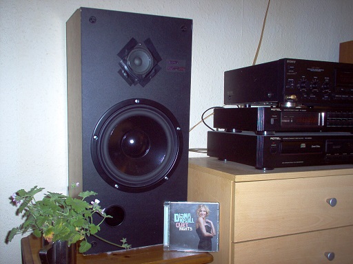
Hi, I'm after some advice or comments.
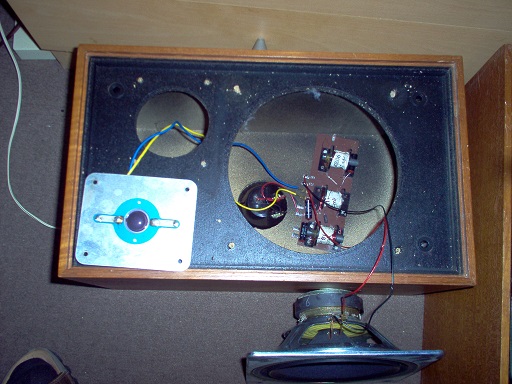
I built some cabinets to suit the Jaycar CW2136 drivers many years ago. Cabinet volume is 33ltr, 66mm port at 165mm length. They sound OK, but I'm looking for advice about some better quality 8" drivers that I could use to replace my existing ones. Drivers suitable for my existing 33ltr cabinets...
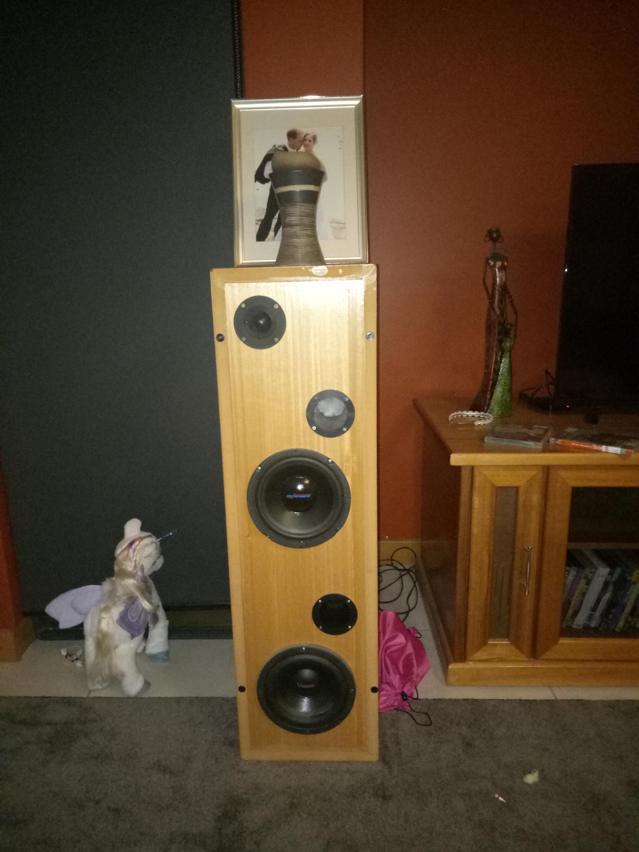
The lower driver in the picture is in a 40ltr separate compartment, and is driven by a separate 300wrms and (sub signals only). The sub is fine, just looking to improve the 8" driver and possibly the tweeter as well. Speakers sound very light sounding and lack bass without the sub woofer being http://www.diyaudio.com/forums/atta...river-replacement-img20180421212441-jpgactive.
Thanks in advance.
As has been mentioned, that tweeter could be closer to the bass. I might turn the whole thing upside down and fit the tweeter in the lower port. Very John Devore! His speakers go for about $5,000.
Last edited:
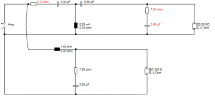
To answer Steve's question about the crossover frequency, 2.8khz sounded quite good to me. I built the passive crossovers at 2.5khz, used my existing former boards and made them. They are very rough at the moment, but they sound great. Bi amping them and running an active crossover allowed me to test different crossover types, slopes etc. But doing this I lost me outside speakers (as they were using my other amp). I've attached a picture of my very rough crossover as per system7s design. To me they sound very flat....
Attachments
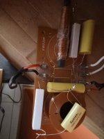
I also used relatively high quality capacitors (250v rated) and, 0.8mm wire to wind both the air core and ferrite inductors. We are in the throws of moving, so as soon as I have a spare minute all post some plots. I use my DSO, with a sweep generator, one channel of the CRO measures the microphone, the other measures the sweep generator (in case the sweep output isn't entirely linear in level). All up the capacitors cost $100 Aussie, former wire was cheap, and obviously the resistors were cheap as chips.
Attachments
Aw, brilliant work, Brett. Your first proper crossover! 250V is normal for MKP capacitors. Actually, cheap non-polars work well enough too. Don't listen to the people who say you need gold capacitors, an' all that nonsense. The crossover circuit is the main event.
I still use that KEF negative polarity idea.
It's not bad for a one-size fits all, eh? I have it running on one of my current 8" plus tweeter speakers. And it's far better than the circuit I found in my old Monitor Audio R300-MD speakers.
Dissi dug up the circuit for the KEF Celeste III, and it's been a constant inspiration. So simple. Of course, ideas evolve. I think I am up to 13 components in my latest effort. But you'd have never built it.
Attachments
I originally wired the tweeters with incorrect polarity, the system actually sounded OK, but the mid-range was very faint... Obviously there was some cancellation due to phase. With the tweeters reversed, the system sounds awesome Was a pain winding the ferrite cores, but once I got one right, I just measured the length of wire, and built two from that which I fine tuned.
Thanks again system7, such a simple circuit but made a massive difference to the sound. I ditched the 22ohm, and used a 2.8series resistor to balance the tweeters. Thanks all again. Now the bug has bit, I may start designing more and more
Was a pain winding the ferrite cores, but once I got one right, I just measured the length of wire, and built two from that which I fine tuned. Thanks again system7, such a simple circuit but made a massive difference to the sound. I ditched the 22ohm, and used a 2.8series resistor to balance the tweeters. Thanks all again. Now the bug has bit, I may start designing more and more
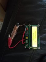
I was very impressed with your engineering ability and especially the use of an inductance meter.
Theory says that inductance is proportional to the square of the number of turns, so you can always unwind an inductor for smaller values too. But you take off less than you might expect...
Nylon zip ties are useful to fix components down to a PCB with a few holes drilled in it. You usually try and arrange coils so they don't share an axis, which you have done correctly.
Tolerances don't matter terribly. 5-10% is usually near enough. You won't hear it. As it goes, the 22R does do something. It slightly damps the tweeter voicecoil, and takes down sibilance. But it's subtle. I always model these things with similar drivers do see how it all works out. The 2.8R protects the amplifier a bit from a resonant short circuit if the tweeter blows at a party.
A$100 seems a lot. Components are expensive in Oz, eh? We in the UK are interested, because we might face a similar situation after Brexit. Or I might just set up a factory...
I am deeply interested in impedance correction at the moment. The easy load for the amp, an' all that. So far, so good.
Hi Steve, I should maybe explain my background... Many years ago I studied and completed a double degree of Electronic engineering and computer system engineering. I focused on radio communications, and now work with ultrasonics, radar, etc in the marine industry. To be honest I should have already thought of impedance matching, phase, and giving the amp as close to a 'constant' load. But after full days at work and dealing with kids etc my brain just has enough. Yes, parts can be expensive here... If I had of ordered them online I would have probably saved a lot, but I like supporting local business. Lately a lot of our work is in the digital domain, meaning the 'dark art' of analog design is slowly dying. I still manually wind crystal/inductor/cap pairs for radios, but as you could guess, at 2-30Mhz, the values are much small (and much more reliant on accuracy of values). I was thinking of placing a large 20ohm 20watt potentioneter in series with the speaker, and driving with 10watts of power from 30hz up to 20khz, using a CRO and accurate DVM I could very accurately plot the impedance curve of the entire system - might be interesting. Thanks for the pointers, that crossover design is so simple, yet works extremely well!!! Thanks, and like I said as soon as we have moved I'll be spending a lot of time plotting the speakers response etc. Can wait to built some more decent speakers
I suppose with two long throw 9" bass drivers, a 7" and a tweeter there is some fairly simple crossovers incorporated. I'm assuming the two 9" are crossed over approx 120hz, with two if them they could afford to be of a lower sensitivity as combined the spl would be much higher. So they are really a 2 way with twin subs per cabinet. I like that as a challenge. I'll build a new front baffle, and I might built mine to look like his prototype, with all the drivers at the front. I'll ditch the sub amplifier and make a while new crossover based on your design. I'll see how tricky I can get. BTW my subs are 4ohm, so Ill see how creative I can get.
Hi again, mate. Sorry I had things to do last night. Actually fiddling around with my current project:
I have been fascinated by the WLM La Scala for years. How do these monkeys charge 2,500 EUros for a speaker with a £10 Visaton TW70 cone tweeter?
It must be good at some level!
So I have had a go at this in Visaton Boxsim.
As Alan Shaw of Harbeth says, the great thing about a CAD simulator on your laptop is you can sit on the beach with the wife, kids, AND a drink, and design speakers too. Win-Win, IMO.
Anyway, here's my suggestion for your next step. Try a Zobel on the tweeter. This is impedance correction for most 6 ohm dome tweeters. It really outpunches its weight. Sounds astonishingly good. IMO. Turns a speaker that sounds OK, into a SMOOTH one that wins a cigar.
Attachments
Last edited:
So they are really a 2 way with twin subs per cabinet.
Closer to home, some of the Osborn speakers are built along the same lines:
Osborn Loudspeakers - The World's Best Hifi Speakers
This review points out that their large speakers are "acting like a small 2 way mini-monitor over most of the musical spectrum"
Osborn Loudspeakers - The World's Best Hifi Speakers | IAR GMR
Osborn = a DIY guy who went pro.
Those Osborn speakers also look amazing. Great to see an Australian making a good go at it
So I've purchased a few books on speaker design, including a book by FANE (I also play guitar so their speakers interested me). Also some books on crossover design etc. Someone mentioned that my speakers suffer from a bit of breakup at approx 2khz. I may even remove the dust caps, and try my hand at making some phase plugs to see if they can fix the issue. I'll do some before and afters....
Sysyem7, the zobel on the tweeter has definitely smoothed them out, WOW was my wife's comment on the difference in sound.
Just a question, baffle backstep literature I have shows a resistor across the inductor on the woofer, I may try winding an inductor by winding 1.0mm wire around the OUTSIDE of a 10w resistor, and try to get a combined inductance of 1.5mH. One of the inductance testers I built allows me to adjust the drive frequency, meaning I can adjust it to 2.5khz and confirm inductance at crossover point. Is there any news for a parallel resistor on the backstep network. I'm also going to remake the front baffle, curve the edges, move the drivers around etc
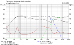
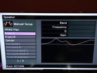
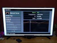
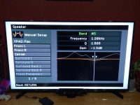
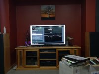
So my speakers as it is have a 2+dB dip at 125hz, and also at 5khz.
Before the crossover corrections they had huge peaks at 125hz, 500hz, and 7khz.
The before plot image is the file name that ends with 5826.
All of these plots are with the lower speaker not connected, and my amplifier in true direct mode (IE what goes in comes out without any eq, tone control etc.).
Attachments
Sorry, I generally write this on my phone, I've noticed its got a habit of changing words for me.... Two of the previous posts were supposed to be questions, not statements. So what in a nutshell, and ideas about baffle step for woofer being wound on a wirewound resistor as a former. I've done this before with carbon resistors (not for audio, but piezoelectric drivers), maybe it won't work due to wirewound resistors already having quite an inductance. My other post that was supposed to be a question and not a statement was about the gibbon x drivers, do you think they have used a low pass filter for the 9" drivers, a band pass for the 'woofer' and a high-pass for the tweeter? Or maybe the two 9" are tuned differently to give a nice even frequency response in the lower frequencies??? Thanks again to all, I'm packing all my gear up to begin the painful task of moving house. More to follow
You do occasionally put a resistor across a bass coil. Maybe 68R or so. But it really doesn't do much. There is a use for, say a 1.5mH coil in parallel with, say 2.2R as passive 2dB bafflestep or tonal shaping. Seas ER18RNX with 27TDFC
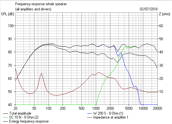
The above sim won't be wildly wrong. A dip at 125Hz is likely a diffraction effect. As is a tweeter dip at 5kHz. I wouldn't worry about either.
John Devore is always a fan of the easy load. But he doesn't go for absolutely flat. Nor do Harbeth. I really couldn't guess the crossover. And I really don't care because I follow my own ideas. Some win a cigar, some don't. It's the hobby. RMAF 2015: DeVore debuts long-awaited Gibbon X production loudspeaker | Part-Time Audiophile
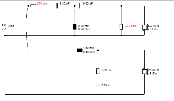
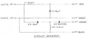
This is a VERY clever circuit:
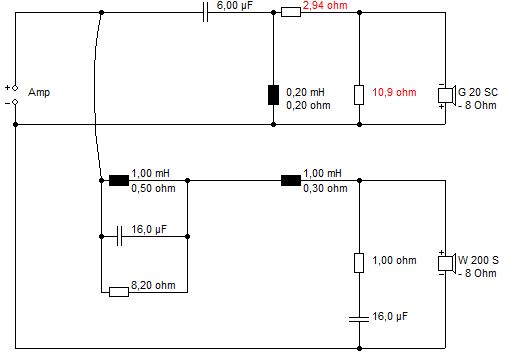
I found that one in an old Wharfedale Shelton XP2. But KEF used it a lot too. A lot of basses have a little shouty 2dB peak around 1.3kHz, and the circuit fixes that. Sounds quite neutral.
From what I can estimate, it will work with most 8" basses. 8 inch basses usually enter breakup around 3kHz, which shows in the phase plot, but it usually is not too offensive.
The above sim won't be wildly wrong. A dip at 125Hz is likely a diffraction effect. As is a tweeter dip at 5kHz. I wouldn't worry about either.
John Devore is always a fan of the easy load. But he doesn't go for absolutely flat. Nor do Harbeth. I really couldn't guess the crossover. And I really don't care because I follow my own ideas. Some win a cigar, some don't. It's the hobby. RMAF 2015: DeVore debuts long-awaited Gibbon X production loudspeaker | Part-Time Audiophile
This is a VERY clever circuit:
I found that one in an old Wharfedale Shelton XP2. But KEF used it a lot too. A lot of basses have a little shouty 2dB peak around 1.3kHz, and the circuit fixes that. Sounds quite neutral.
From what I can estimate, it will work with most 8" basses. 8 inch basses usually enter breakup around 3kHz, which shows in the phase plot, but it usually is not too offensive.
Last edited:
System7, you are a wealth of information!
I watched the Harbeth link you sent, and found some others to watch as well. Very clever man, I guess with 40years of speaker design behind him he would know an awful lot about speakers, crossovers, cabinets and what 'sounds'good. I particularly like his comments about recorded voice, Very interesting!
I'm still tinkering...
I've fabricated new front and rear baffles, the font bring the 8" driver and the tweeter closer together. I'll fire the two ports rearward, and I'm going to add another 8"driver for the sub 120hz signals. The venom sub that I have is was very cheap, and is probably quite poor quality, but I figure if I keep tuning the lower cabinet till I get a nice roll off, I should end up with a nice sound.
Either that or I buy some decent drivers. The visaton drivers look very nice.
What's everyone's opinion on ribbon tweeters, or decent quality tweeters?
Thanks again to all for the advice 👍
- Status
- This old topic is closed. If you want to reopen this topic, contact a moderator using the "Report Post" button.
- Home
- Loudspeakers
- Multi-Way
- 8" speaker driver replacement