Hello,
I've got an aged pair of Heybrook Sextets and as a result of an incident with a cat's claw and a Tonegen (Infinity EMIT-K) ribbon tweeter, coupled with age I now find myself with substituting these units for something more modern.
In keeping with the ribbon theme I've gone for the well respected Fountek NeoCD1.0, firstly I simply replaced the tweeter leaving the crossover intact to see where to start, let's just say it was a little bright! Doing a frequency sweep and comparing to the working Tonegen I was staggered at the range the Fountek had, it was going all the way down past 600hz when I decided to stop, the Tonegen had rolled off at around 1600-1800hz.
So keeping the Peter Comeau's 1st order intact I decided to replace the 2.2uf capacitor with a 4.7uf (Mundorf MCap Oil), this improved the roll-off but it still a little caused me a little concern. I then made the decision to use a 2nd order LR (3.3uf and 0.33mH) which worked well, rolling off better and providing some more protection.
The Fountek was still bright, however it and the replacement caps in the crossover are new so I decided to leave it a few hours to bed in and 'calm down' a bit, which it did, in the last day or so I started into introduce a 3.3ohm resistor before the cap which has helped and to be honest is sounding quite wonderful for a early install, pre-full bedding in.
I've left the woofer and mid alone, they are the standard Seas units. The resistor and caps in the crossover have been replaced with same value items, albeit with the entire crossover now mounted externally.
Could someone tell me if the values I've used in the HF crossover and the placement of the attenuating resistor are good to go and my ears aren't deceiving me.
Many thanks!
I can't imagine anything in a capacitor "beds down" unless the electrons are getting sleepy... really! 
Homework:
www.audioexcite.com >> Fountek NeoCD1.0
Speedster - undefinition
NeoCD1.0
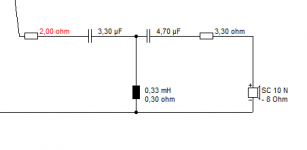
Fragile, isn't it? 3.5kHz third order recommended. 3.3uF and 0.33mH is your standard 8 ohm 3kHz second order. Maybe 4.7uF and 0.2mH is better for 5 ohms. And 3.3R in front of that ought to pad it down about 3dB.
So, you are on the right track here. I don't suppose the overall setup will end up much different from this for a 6" plus 5" plus 3.5kHz tweeter:
SEAS-3-Way-Classic
Homework:
www.audioexcite.com >> Fountek NeoCD1.0
Speedster - undefinition
NeoCD1.0
Fragile, isn't it? 3.5kHz third order recommended. 3.3uF and 0.33mH is your standard 8 ohm 3kHz second order. Maybe 4.7uF and 0.2mH is better for 5 ohms. And 3.3R in front of that ought to pad it down about 3dB.
So, you are on the right track here. I don't suppose the overall setup will end up much different from this for a 6" plus 5" plus 3.5kHz tweeter:
SEAS-3-Way-Classic
I can't imagine anything in a capacitor "beds down" unless the electrons are getting sleepy... really!
Homework:
www.audioexcite.com >> Fountek NeoCD1.0
Speedster - undefinition
NeoCD1.0
Fragile, isn't it? 3.5kHz third order recommended. 3.3uF and 0.33mH is your standard 8 ohm 3kHz second order. Maybe 4.7uF and 0.2mH is better for 5 ohms. And 3.3R in front of that ought to pad it down about 3dB.
So, you are on the right track here. I don't suppose the overall setup will end up much different from this for a 6" plus 5" plus 3.5kHz tweeter:
SEAS-3-Way-Classic
LOL, I know what you mean.
Thanks for those links, really appreciate it.
I think you can pretty much treat it like any old 5-6 ohm 90dB tweeter on a third order 3-3.5kHz crossover. Resistor adjust in front of network.
Many ways to skin a cat.
3.9R/3.3uF/0.2mH/10uF (KEF)
3.9R/4uF/0.2mH/4uF (KEF)
3.9R/4uF/0.2mH/6uF (Celestion)
With a second order, you shouldn't drive it too loud. How it works.
Many ways to skin a cat.
3.9R/3.3uF/0.2mH/10uF (KEF)
3.9R/4uF/0.2mH/4uF (KEF)
3.9R/4uF/0.2mH/6uF (Celestion)
With a second order, you shouldn't drive it too loud. How it works.
I think you can pretty much treat it like any old 5-6 ohm 90dB tweeter on a third order 3-3.5kHz crossover. Resistor adjust in front of network.
Many ways to skin a cat.
3.9R/3.3uF/0.2mH/10uF (KEF)
3.9R/4uF/0.2mH/4uF (KEF)
3.9R/4uF/0.2mH/6uF (Celestion)
With a second order, you shouldn't drive it too loud. How it works.
Thanks again, I'll have have to do some homework on 3rd order crossovers.
That Speedster link is tempting....and I don't need another set of speakers!
I use Visaton Boxsim. Software | Visaton
It's quite easy to set up a box, choose some similar drivers and place them on the baffle. Then do a crossover and optimise it.
You can even shortcut by importing a projekte into the bpj folder that does most of what you want and modify it:
3 Wege – Boxsim Projektdatenbank
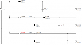
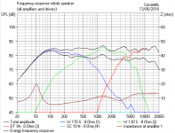
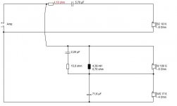
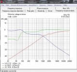
I found that about 6.2R/3.3uf/0.2mH/10uF does the right things for you. 6.2R/4.7uF/0.2mH/4.7uF (dotted) has worse impedance although it is flatter. The 15R is just a modelling device to get the tweeter to 5 ohms and is not fitted.
It's quite easy to set up a box, choose some similar drivers and place them on the baffle. Then do a crossover and optimise it.
You can even shortcut by importing a projekte into the bpj folder that does most of what you want and modify it:
3 Wege – Boxsim Projektdatenbank
I found that about 6.2R/3.3uf/0.2mH/10uF does the right things for you. 6.2R/4.7uF/0.2mH/4.7uF (dotted) has worse impedance although it is flatter. The 15R is just a modelling device to get the tweeter to 5 ohms and is not fitted.
Attachments
... Or you could use XSim, measure your drivers and do it properly.
Steve, I get that you find the results acceptable, but randomly substituting drivers into a simulation program is not the way to get accurate results.
Damian, larger capacitor values means the ribbon is playing lower down the frequency range. I'd put the cap back to how you found it, and then add a resistor or L-pad to attenuate the new ribbon.
Chris
Thanks guys, time to start playing again. How do you put the worms back in the can?
The perfect is always the enemy of the good. Because it never arrives...
Whatever method you use, it will always end up as three or four components here. We don't need microphone measurements, because the manufacturer supplies them.
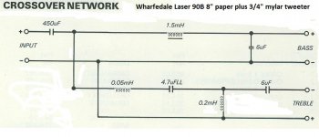
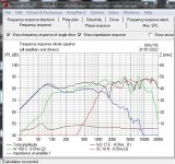
Tweeter filters are terribly simple. Seen one, you seen them all. Here's a nice simple ca. 3.2kHz Wharfedale Laser 90B filter for an approx. 87dB 3/4" plastic tweeter that behaves much like your ribbon except on loudness.
It even has a bright top end, which Wharfedale have fixed with a little coil. It's not a biggie really. A slightly absorbent grille cloth and some off-axis listening sounds much the same.
I find my sims work incredibly well for establishing the overall features. And spotting some rank bad design on occasion. But people don't want to hear their dream speaker is full of schoolboy mistakes. So criticise my methods. But, IMO, the main thing is to understand the tools you work with.
Any damn fool can get a flat frequency response on axis. I take it further and look for good power response and easy impedance and flattish drivers in their comfort zone. Oh yes, some people claim impedance and phase angle doesn't matter. I think it does. Amps don't like driving a low or capacitative load.
BTW, check your polarities here. They may have changed from when you had a single 2.2uF cap and the Tonegen ribbon.
Attachments
BTW, check your polarities here. They may have changed from when you had a single 2.2uF cap and the Tonegen ribbon.
Moving to a 2nd order means you swap the polarity right?
90% of speakers use positive polarity between the mid or midbass and the tweeter.

That is your standard 3 way on a flat baffle. Phase alignment is good.
With a second order filter on the tweeter, it's not so tidy, tending to a butterworth 90 degrees. But still +--. A single cap tweeter might be wired +-+. TBH, best to model it.
The Wharfedale Laser 90B is +- because an 8" bass has a time alignment error approaching 1/2 wavelength at 3kHz, or 5cms. Complicated, isn't it? You can hear wrong phase alignment. It sounds hollow, phasey or lacking in pinpoint imaging. 3Khz is around about the harmonics of electric guitar, like Dire Straits. Wrong polarity would have an echoey sound. Best I can describe it.
Reviving the thread and hopefull system 7 you can comment. I am upgrading a set of Heybrook 11 and I have the schematic only the mid arrangement seems odd. I've checked and this is definitely how it is wired. Also the tweeter has the resistors in series with the caps, not to ground.

I'm not sure what a Heybrook 11 is exactly, but appears to be a 6" polycone bass, 5" mid and 1" Tonegen tweeter:
Series filter between bass and mid.
Useful homework here:
http://www.troelsgravesen.dk/33FWK.htm
http://www.troelsgravesen.dk/HES.htm
Ran the sim, with similar drivers, and it's quite odd...
I think I could do better.
Series filter between bass and mid.
Useful homework here:
http://www.troelsgravesen.dk/33FWK.htm
http://www.troelsgravesen.dk/HES.htm
Ran the sim, with similar drivers, and it's quite odd...
I think I could do better.
Attachments
My Bad. Heybrook Sextet II. Correct it is those drivers, the actual driver part codes are in the diagram above and I agree you may be able to do better. The suck out your sim shows for the total drivers seems to match the listening experience btw. The Tonegen driver is lower resistance 4 ohms I believe. your sim has 5.7 ohm in series with the tweeter, I found 5.9uf. The mid is sealed. The bass ported.I'm not sure what a Heybrook 11 is exactly, but appears to be a 6" polycone bass, 5" mid and 1" Tonegen tweeter:
Series filter between bass and mid.
Useful homework here:
http://www.troelsgravesen.dk/33FWK.htm
http://www.troelsgravesen.dk/HES.htm
Ran the sim, with similar drivers, and it's quite odd...
I think I could do better.
Last edited:
I can't imagine anything in a capacitor "beds down”
A capacitor is a mechanical construction. The layer sof the cap stretch, move, “bed-in” as voltage is first applied. This can be audiable.
dave
Series filter between bass and mid.
Series would require a shunt across the mid. It has only series components. But the mid is in series with the woofer.
It is strange and i am still digesting it.
dave
Last edited:
I redrew it so as to make it clearer. Series connection, only a countour filter. The shunt acroos the woofer filters out the HF from the woofer, the mid will have natural roll-off at the top and whatever 2nd order filter comes from a sealed enclosure onthe mid. The HP on the woofer will be second order electrical (midified by the CR shunt across it)

dave
dave
That circuit of yours will be a dead short at high frequency, Mr. Dave...
The big shunt capacitor will do that. I didn't find the 2.2uF and 15R actually did much. Just rolls off the bass a bit at HF.
Curt Campbell does something similar in the Halcyon:
http://speakerdesignworks.com/Halcyon_4.html
Have tracked down the bass and mid I think:
http://www.seas.no/images/stories/vintage/pdfdataheet/h0571_cb17rcyp.pdf
http://www.seas.no/images/stories/vintage/pdfdataheet/h0422_mp14rcy.pdf
The polycone mid has tidy rolloff above 3kHz. The (paper?) bass is smooth enough. Not sure if the bass is 4 ohms. That would be unusual for SEAS.
I can see how it works. But still don't like the ribbon on first order.
- Home
- Loudspeakers
- Multi-Way
- Sanity check for a 'newbie' Heybrook Sextet ribbon tweeter replacement