I've been experimenting with Lenard Audio's TL software, with the observation that a tower's elongated shape may lend itself to transmission line modeling, even though the design itself is not tuned to be a TL.
Let's say the tower is 1m tall, and when the woofer is placed at somewhere near 0.47m or 0.48m, the first harmonic (not sure what it is really called) is significantly suppressed, which is great news. I found no other value, other than the opposite side of the symmetry (0.52m-0.53m) would have equal suppression. I have no understanding of TL theory but intuitively if a standing wave develops you don't want your driver to be halfway in between where it is a low pressure null point but you want to move it a few percent off instead.
Now add a port to the tower. 0.48m driver and port at 1m works equally great, but now the symmetry 0.52m looks terrible. Why would that be so?
Your example model changes greatly because you are fundamentally changing the way the enclosure works. By sticking a hole/port tube at or near one end you are opening the pipe at that end, promoting the generation of 3rd,5th,7th harmonic modes. Much information on mostly "edu" sites on the web about closed, semi-open, fully open pipes and harmonic modes.
J.
J.
When the internal height of the enclosure is in the range of 36" to 40", placing the woofer, or midwoofer, with its center 7" to 9" below the internal top of the enclosure usually works out very well, along with a port whose center is located 3" to 5" above the internal bottom of the enclosure. This creates a version of a mass-loaded TL (ML-TL).
Paul
Paul
Sorry Dave but this is not really a TL but both ends are closed. Is it still going to be 0.336? (I vaguely remember that number from Martin J. King's paper.)
When I first joined I was surprised everyone's working on either a horn or a TL or both (like the Frugel-Horn). Is it because traditional design has become too easy and many of you could do it blind-folded and you need a more challenging frontier? Well, maybe that is part of the reason, but by now I begin to appreciate what is going on - that once you define a specific set of design goals there are certain topologies which could give you precisely the result you want or give you a specific sound that you are after.
So, at least it sounds like I am not on the wrong track and it was worthwhile to explore what a sealed or vented box would simulate like with a transmission line model.
Your example model changes greatly because you are fundamentally changing the way the enclosure works. By sticking a hole/port tube at or near one end you are opening the pipe at that end, promoting the generation of 3rd,5th,7th harmonic modes. Much information on mostly "edu" sites on the web about closed, semi-open, fully open pipes and harmonic modes.
J.
Thanks very much J. that's very insightful. Here are what I have gathered with the simulator so far:
- 0.47-0.48 appears true for a sealed box and the right ballpark for vented. The port tuning affects the position a little bit, but not very much.
- I created a "branch" to put the port at various positions and virtually all of them have very strong 3rd, 5th and 7th harmonics. Is there some magic position to put the port to reduce those? (Could be port-tuning dependent, I don't know.) Or are they supposed to have to be tamed by stuffing?
When the internal height of the enclosure is in the range of 36" to 40", placing the woofer, or midwoofer, with its center 7" to 9" below the internal top of the enclosure usually works out very well, along with a port whose center is located 3" to 5" above the internal bottom of the enclosure. This creates a version of a mass-loaded TL (ML-TL).
Paul
Thanks Paul, I have always been intrigued by ML-TL. If I am understanding correctly both ends are closed, but it is ported at one end? The point is to tune to 1/4 wavelength and use that to help the port so that it can be much shorter (or much wider opening) than it would otherwise be?
If it is closed at both ends then it is a half-wave TL, not the common quarter wave TL.
dave
Thanks Dave. I was not attempting a TL design, but putting a sealed tower through a TL sim. The motivation is that while traditional box software tells me everything about box volume and port tuning, it assumes the driver can be put anywhere on the box. There must be some optimal position to place the driver and I am trying to learn that.
(1m would have been a really high frequency for 1/2 wave and very much away from the Fs of the driver.)
Last edited:
Sorry... I tried a sealed box first and then added a port to it and see how it went.
BTW, incidental to this... Is the length of a ML-TL still 1/4 wave?
Anyway please forget the 0.48 figure. For sealed and for vented where the air volume in the port is insignificant compared to the box volume the optimum position is 0.5. This is based on the assumption that higher harmonics are easier to absorb by stuffing so the aim should be to eliminate the first harmonic.
Last edited:
0.5 is optimum for a closed pipe; add a vent and it shifts to an odd harmonic, though it shifts down the pipe a little due to the vent, so 1/5 = ~0.21, 1/3 = ~0.349, 2/5 = ~0.424, which is as far down as one would normally want to go for a straight pipe. Vents work well at 4/5 = 0.848 and near/at the bottom as Paul noted.
Re a typical cubic or rectangular cab where its air mass has a ~uniform particle density, driver down ~0.424 is optimum for both sealed, vented and the vent can be anywhere on the cab since it's a simple Helmholtz regulator.
Yes, it'a 1/4 WL resonator and the vent is a 1/2 WL resonator. Note that for a MLTL to get enough vent damping to audibly effect vent length [shortens it compared to predicted for a given tuning], the cab needs to fairly long, so look for at least a 5 Hz lower tuning than predicted for a simple reflex. The 60+" cabs I normally spec usually require going to a much larger vent just to be long enough as a hole in ~3/4" thick baffle.
GM
Wow, that was exactly the information I needed. Thank you!!!
May I ask one more question?
Is there any rule saying the cross section along the entire line must exceed 1 * Sd at any given point? (It was just my intuition that otherwise the line will be operating as a horn-loaded compression driver in reverse, so maybe it is just me making this up.)
May I ask one more question?
Is there any rule saying the cross section along the entire line must exceed 1 * Sd at any given point? (It was just my intuition that otherwise the line will be operating as a horn-loaded compression driver in reverse, so maybe it is just me making this up.)
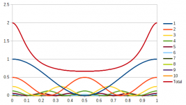
Prompted by your valuable responses I tried to model standing waves in... LibreOffice.
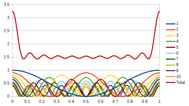
The chart plots the sum of the first 10 harmonics but not all are given equal weighing. 100% for n=1, 90% for n=2, 81% for n=2, and so on. You would want to place the speaker at one of the minimums.
Long story short, the take away is, other than the beginning or the end, there is virtually no bad place to be.
The number of ripples in the sum has no significance. I added the first 10 harmonics so there are 10 ripples. It follows that if an infinite number is summed the ripples would average and become a straight line.
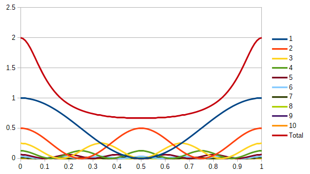
If I change the weighing so that it is 50% for n=2, 25% for n=3, and so on, the curve becomes a simple bowl shape, favoring placement at 0.5m.
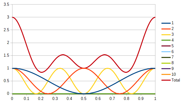
If we give equal weighing for the first 3 and completely ignore the others, 0.21m is a great place to be, and that might have been where one of GM's magic numbers came from.
I have zero idea how the weighing is supposed to be assigned, and that obviously depends heavily on the stuffing (amount and type). All in all, this exercise explains why we were taught the cabinet dimensions must not be rational ratios of each other, but we were not typically told about any special position for driver placement, other than taking diffraction into account by offsetting.
If we have to find some magic numbers anyway, here is a list when we consider only the first n harmonics, giving them equal weighing, and ignore all higher ones above n. This may not be realistic as no stuffing material has such property, but is useful if you specifically want to minimize lower harmonics but ignore the higher ones.
1 or infinite: 0.5
2: 0.29
3: 0.21, 0.5
4: 0.16, 0.39
5: 0.13, 0.32, 0.5
The chart plots the sum of the first 10 harmonics but not all are given equal weighing. 100% for n=1, 90% for n=2, 81% for n=2, and so on. You would want to place the speaker at one of the minimums.
Long story short, the take away is, other than the beginning or the end, there is virtually no bad place to be.
The number of ripples in the sum has no significance. I added the first 10 harmonics so there are 10 ripples. It follows that if an infinite number is summed the ripples would average and become a straight line.
If I change the weighing so that it is 50% for n=2, 25% for n=3, and so on, the curve becomes a simple bowl shape, favoring placement at 0.5m.
If we give equal weighing for the first 3 and completely ignore the others, 0.21m is a great place to be, and that might have been where one of GM's magic numbers came from.
I have zero idea how the weighing is supposed to be assigned, and that obviously depends heavily on the stuffing (amount and type). All in all, this exercise explains why we were taught the cabinet dimensions must not be rational ratios of each other, but we were not typically told about any special position for driver placement, other than taking diffraction into account by offsetting.
If we have to find some magic numbers anyway, here is a list when we consider only the first n harmonics, giving them equal weighing, and ignore all higher ones above n. This may not be realistic as no stuffing material has such property, but is useful if you specifically want to minimize lower harmonics but ignore the higher ones.
1 or infinite: 0.5
2: 0.29
3: 0.21, 0.5
4: 0.16, 0.39
5: 0.13, 0.32, 0.5
Attachments
Last edited:
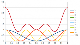
Another way to place the driver is to simply use any rational ratio, like 0.5, 0.33, 0.25, 0.2, 0.4, etc.
Summing may reduce the overall result but may accentuate certain harmonics. For example, when position is at 0.5, n=1 is minimized but n=2 is maximized. Sometimes it may be desirable to even out the anomalies even though it may mean the total as measured by summation may be slightly worse (again, ignoring the higher harmonics). If that is the case, 0.25 and 0.4 look good, as can be seen in the 3rd graph.
Summing may reduce the overall result but may accentuate certain harmonics. For example, when position is at 0.5, n=1 is minimized but n=2 is maximized. Sometimes it may be desirable to even out the anomalies even though it may mean the total as measured by summation may be slightly worse (again, ignoring the higher harmonics). If that is the case, 0.25 and 0.4 look good, as can be seen in the 3rd graph.
Last edited:
One example to try in TL.
Dayton DA175
120cm pipe, both ends closed.
308cm2 cross section.
Port/branch of 32cm2 x 20cm @ 105cm/15cm. (68mm mini guttering downpipe in upvc).
Stuff @ 3kg/m3 for the first 105cm. Play with the stuffing densities above 2kg/m3 to alter the "slope" of the bass output..
Try the driver at 30cm and at 57-58cm.
With a single DA175 playing down to 30Hz, maximum SPL will be low (dependant on source material). group delay is quite low around 50hz however. Use it with a subsonic filter or with most music and it'll be fine. Or use it with a subwoofer for loud action movies.
2 way DA175 designs I have seen have been MTM. (Zaph audio bargain aluminium MTM).
A single DA175 might be matched to a wide ranger like the FR58EX if SPL requirements are modest. i.e not a church hall.
J.
120cm pipe, both ends closed.
308cm2 cross section.
Port/branch of 32cm2 x 20cm @ 105cm/15cm.
Again contradictory information. The port makes for one end open.
dave
Again contradictory information. The port makes for one end open.
dave
It's more LATL speak than the physics of pipe modes.
- Status
- This old topic is closed. If you want to reopen this topic, contact a moderator using the "Report Post" button.
- Home
- Loudspeakers
- Multi-Way
- Adventures modeling a tower as a TL