Hello everyone
what I ask and to know if the Le of the D54AF is equal to 0.2 as I would like to add the relative Zobel.
it seems unlikely that it is measured at 10Khz when the answer does not exceed 6 Khz, undoubtedly it is an error, so I ask you what its true value is.
the second question is to know what the exact formula for calculating zobel is.
some say that the king must be equal to the resistance to be included in the zobel, others say it must be superior.
can you give me the appropriate information?
thanks and bye
Attachments
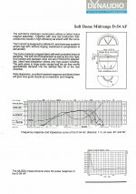
The datasheet is showing Z=16ohm at 10kHz therefore if Re=4.5ohm, Le=16-4.5=11.5ohm
11.5/(2*pi*10K) = 0.18mH
You can also do it for other frequencies by looking up the impedance on the plot and calculating Le again. At 5kHz you get 0.09mH and at 20kHz you get 0.32mH. This is because the inductive part of the impedance is not an ideal inductor, it's lossy. Because of this there is no 'perfect' zobel, simply one that it makes the impedance flattest through a certain range of frequencies that is up to you to choose.
I would sim the zobel in a crossover simulator like XSim loaded with the measured driver impedance. Start with R=Re, C=0.1uF. Increase C until the impedance becomes flat through a useful range of frequencies (e.g. 1-5kHz for the D54). If the resulting impedance becomes too low for your liking then increase R and adjust C again.
Last edited:
Hi,
After reading TMM's reply I would humbly suggest TMM has offered correct and valid information. The spec sheet gives Z as 8 Ohms, however if you look at the frequency impedance chart you provided the Z at 10Khz is in fact 16 ohms.
TMM has then shown his calculations and provided what the calculated LE is at a few frequencies.
You can apply the same calculation for the le at 6Khz if that is your design crossover frequency. His further advice is practical if you use a crossover simulator where you can model the effect of differing C's and R to give a flat impedance response.
Last edited:
The datasheet is showing Z=16ohm
Z= 8ohm!!!!!!!!!!!!!!!!!!!!!!!!!!!!!!!!!!!!!!!!!!!!!!!!!!!!!!!!
Look again. Impedance curve traced in green. 16ohm level in pink. The impedance at 10KHz circled in blue is 16ohms, as TMM said.
Attachments
The D54 AF would most likely be crossed over to a tweeter at 3 to 4 kHz. In this range the impedance is close to the specified nominal value and a correction network is not of much value, especially if an 'L' pad is needed to adjust sensitivity of the mid-range unit to match the bass speaker. If a series R.C. impedance network is needed and this is more likely the case for a bass speaker xover, then follow this earlier forum. http://www.diyaudio.com/forums/multi-way/305547-zobel-5-print.html
The datasheet is showing Z=16ohm at 10kHz therefore if Re=4.5ohm, Le=16-4.5=11.5ohm
11.5/(2*pi*10K) = 0.18mH
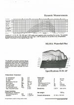
Hi, actually this is not the correct procedure for calculating inductive reactance even though you could get lucky sometimes and come up with similarly good results. The proper way would be to solve for the imaginary part of Z by including the phase angle at the desired frequency. I have my own data for Dynaudio D 52 AF:
1,000 Hz; Z=6.39; phase=1.28 deg
10,000 Hz; Z=14.22; phase=42.11 deg
In some older books the theory on doing these calculations is also wrong.
Much above Fs the impedance is virtually completely Re + Le only, therefore subtracting Re which is constant you get the impedance contribution from Le. The inductive component is so lossy (Le begins to have its own resistive component) and frequency dependent in a dynamic speaker driver that technically there is no "correct" way of assigning a mH value to Le. If you ignore the resistive contribution of Le (let's call it Rle) then calculating a theoretical zobel will result in an impedance of Re+Rle instead of just Re.
Either way, a simple RC zobel can't flatten a lossy inductance perfectly across all frequencies anyway.
Using the entire impedance sweep in a simulator is the most correct way to design a zobel/crossover etc.
Either way, a simple RC zobel can't flatten a lossy inductance perfectly across all frequencies anyway.
Using the entire impedance sweep in a simulator is the most correct way to design a zobel/crossover etc.
Last edited:
TMM if you apply the same definition as Joseph D'Appolito and others use, Re and Le are the blocked values found when the cone is prevented from moving. Lojzek has detailed it all correctly. In fact a simple series RC network does flatten the impedance if you use the phase angle and impedance measured at the desired crossover frequency for the speaker requiring correction.
- Status
- This old topic is closed. If you want to reopen this topic, contact a moderator using the "Report Post" button.
- Home
- Loudspeakers
- Multi-Way
- D 54 AF