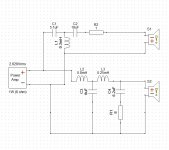
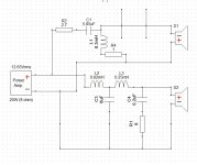
So, update time, I guess. It's been a wild ride. Went through at least a couple dozen crossover revisions, decided that it would be best to use the PA-380-8 as an active sub with LPF, and use a full third-order crossover between the (now full-range FE166En) and tweeter crossing at 2.6kHz. Also added a 1 ohm resistor in series with the NeoCD3.5H ribbon tweeter to bring the nominal impedance up from 7 to 8 ohms.
It works. It really, really works. The midrange presentation is slightly recessed, but the driver integration is miles better than anything I've worked on before.
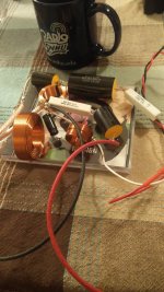
Attached is a photo of the (somewhat messy) crossover glued to an Ace of Base CD cover.
It works. It really, really works. The midrange presentation is slightly recessed, but the driver integration is miles better than anything I've worked on before.
Attached is a photo of the (somewhat messy) crossover glued to an Ace of Base CD cover.
Attachments
The 550uH coil in parallel with the tweeter(Post #1) has essentially muted it out...dropping 20dB or more.
That's microhenries, which is 0.55mH. It was fine and it worked okay-ish. Settled on a third-order crossover at 2.6kHz using a 5.1uF cap, 18uF cap and 0.3mH (300uH) inductor.
A variation...
Where did you get the FRD/ZMA files? I've been looking all over for them. Also, unfortunately, I think I might have to keep the high pass as a third-order to avoid frying the ribbon if I want the full 15W output. Manufacturer recommends 2500Hz third-order, or thereabouts.
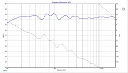
Also, what does the phase plot look like?
I definitely appreciate the help!
Last edited:
Where did you get the FRD/ZMA files? I've been looking all over for them. Also, unfortunately, I think I might have to keep the high pass as a third-order to avoid frying the ribbon.
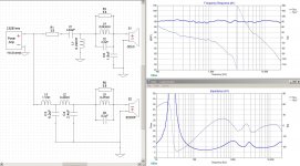
I scanned the driver graphs with "SPL Tools" in Vituix CAD and made my own frd & zma files. Your schematic will fry the tweeter, my version will not. You can check this in XSIM by cranking up the power amplifier and adding a "Component Power Dissipation Graph" option to observe the hot spots in your crossover and the driver components. Regardless, you seem to be on the right track...
I scanned the driver graphs with "SPL Tools" in Vituix CAD and made my own frd & zma files. Your schematic will fry the tweeter, my version will not. You can check this in XSIM by cranking up the power amplifier and adding a "Component Power Dissipation Graph" option to observe the hot spots in your crossover and the driver components. Regardless, you seem to be on the right track...
Awesome, thank you!
Not perfect by any means but good enough to get a better simulation than no frd/zma. I made these quick on the run but if it was my speaker design, I would slow down and craft much better frd/zma files. Chop off the .txt ending for use in XSIM.
Attachments
Last edited:
Many times the driver manufacturer's data sheets have poor quality graphs to extract the data from. I have had great success several times getting better data just by asking the OEM. In some cases the speaker maker sent me laboratory frd & zma files from their own archives. Lets face it, they DO want you to use their equipment.
When I am in a rush or better data does not exist, I load the graphs into Photoshop and make them large and pretty so they scan more accurate in whatever graph extraction tool I am using. I think Microsoft Paint can also do a fine job if you can get the hang of it?
When I am in a rush or better data does not exist, I load the graphs into Photoshop and make them large and pretty so they scan more accurate in whatever graph extraction tool I am using. I think Microsoft Paint can also do a fine job if you can get the hang of it?
Last edited:
...unfortunately, I think I might have to keep the high pass as a third-order to avoid frying the ribbon if I want the full 15W output. Manufacturer recommends 2500Hz third-order, or thereabout...
The series resistor in the tweeter's crossover can be dramatically adjusted to increase the power handling of the tweeter. It could be 5 or 6 ohms without destroying the sound quality but those tweaks are usually fine tuned when you have the speakers up and running. Then you really know what to tweak...

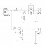
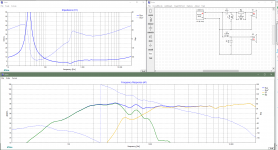
i played a bit with the files you posted and i actually get the best result crossing way lower than you did, at 800Hz. You crosover in the middle of the cone breakup of that driver, wich gives you the ragged response you got. This is my result that i like the most...
Off course you need to check if your driver actually can go that low without being destroyed. But i think that midrange is not fit for that tweeter, and you need to push the tweeter too low to get out the the cone breakup region of that midrange.
Off course you need to check if your driver actually can go that low without being destroyed. But i think that midrange is not fit for that tweeter, and you need to push the tweeter too low to get out the the cone breakup region of that midrange.
Attachments
Last edited:
Off course you need to check if your driver actually can go that low without being destroyed
I hear ya. The ribbon tweeter would be dead in 5 minutes using your circuit. You can do quick sanity checks with the 'power graph' option and tweaking the 'power amplifier' in XSIM to see such design flaws.
Alekk has an odd selection of drivers to create this project. In my view none of them play well together. I guess if you use DSP everything works these days?
It's fun stuff to mess around with.I have been using Fountek ribbons for a few years. I have had great results but in the beginning there was a bit of a learning curve. I saw Alekk's CD3.5(a driver I have yet to use) and it compelled me to hack something together. Those files I uploaded are rough around the edges so if somebody plans to use them to design an actual system, they'd be better off starting from scratch. Cheers.
i played a bit with the files you posted and i actually get the best result crossing way lower than you did, at 800Hz. You crosover in the middle of the cone breakup of that driver, wich gives you the ragged response you got. This is my result that i like the most...
Off course you need to check if your driver actually can go that low without being destroyed. But i think that midrange is not fit for that tweeter, and you need to push the tweeter too low to get out the the cone breakup region of that midrange.
Yeah, the issue is not just the ribbon, but also the transformer, which has a DC resistance that's almost a dead short (0.02 ohms). For testing purposes only, the largest value capacitor in series with the tweeter has to be less than 10uF (up to 1W).
The sort-of rocky response at 1-2k is pretty common with these Fostex full-range drivers, as they sacrifice flat response for higher sensitivity, and I'm fine with that. They do start beaming at around 2.5kHz, which is why I tried to keep the crossover as low as possible (2500Hz, 15Wrms power handling).
Also that phase plot gives me anxiety.
I hear ya. The ribbon tweeter would be dead in 5 minutes using your circuit. You can do quick sanity checks with the 'power graph' option and tweaking the 'power amplifier' in XSIM to see such design flaws.
Alekk has an odd selection of drivers to create this project. In my view none of them play well together. I guess if you use DSP everything works these days?
I have been using Fountek ribbons for a few years. I have had great results but in the beginning there was a bit of a learning curve. I saw Alekk's CD3.5(a driver I have yet to use) and it compelled me to hack something together. Those files I uploaded are rough around the edges so if somebody plans to use them to design an actual system, they'd be better off starting from scratch. Cheers.
The 3.5H was my choice as the lil' CD horn intrigued me. The 15 degree off-axis response is right on the money, so they can be pointed straight out into the room.
The Fostex FE166En is a bit of a black sheep in their full-range driver lineup, but the extremely lightweight cone (relative to its size, 5.9g moving mass!) seemed like the way to go when integrating with a ribbon tweeter. Essentially, I wanted something 2-way that has high-ish sensitivity that could be paired with a SE tube amplifier (or the strung-out JLH downstairs).
As long as I'm close to +-3dB, it's alright. I'm not mixing on them (that's what the headphones are for), so a little lumpy bumpy is okay with me.
Last edited:
So! This is what I have in the parts bin, and I'm gonna give it a try. Didn't have the LCR components, so I'm gonna leave it out for now. Phase plot looks good, as does dissipation.
Edit: Swapped the 2.7 ohm resistor for a 2.4, as it is what I have on hand.
Edit: Swapped the 2.7 ohm resistor for a 2.4, as it is what I have on hand.
Attachments
As long as I'm close to +-3dB, it's alright.
Absolutely. People see it on paper and it drives them crazy. They can often come to quick and harsh assumptions. Ha ha people are people...
Imagine if you had an E220CF-8 to go with that tweeter?
Imagine if I had another 600 dollars.
- Status
- This old topic is closed. If you want to reopen this topic, contact a moderator using the "Report Post" button.
- Home
- Loudspeakers
- Multi-Way
- Troubleshooting A Tricky Crossover