We are all toilers in the Vinyard of loudspeakers... 
Mere mortals attempting to make sense of the pattern.
IMO, this is a pretty good attempt at a goodish loudspeaker. I had a rare success at predicting the 10-1 winner of a tough race today. I thought Tiger Roll might win the tough Grand National. I would never put my money on a bet for this, because Da Bookies always win, but am experienced enough to notice that a relatively young (8-y-o) and lightly handicapped (10St-13Oz in our bizarre British units) horse might win. So it turned out.
I won't currently attempt to dissect that complex crossover. TBH, I'm not expecting it to defy the laws of physics. I know how those work. YouTube
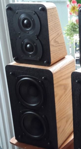
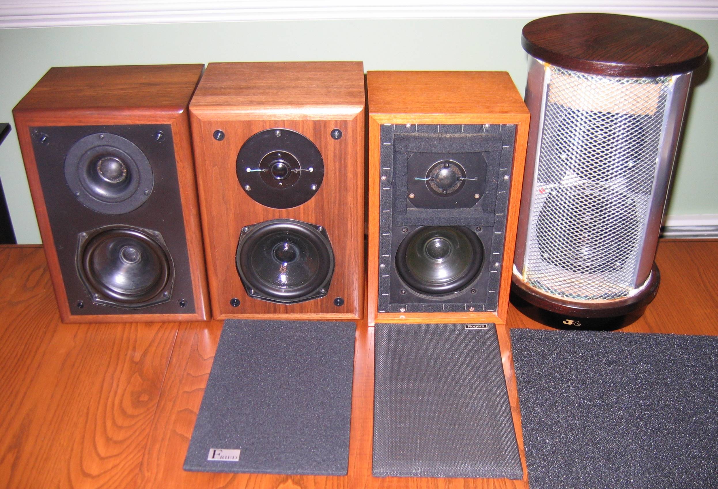
I have seen various attempts on the 5" polycone plus 1" tweeter theme:
Doubling them up is a good approach if you have money to burn. What causes distortion is displacement. Free a mid from bass duties and it sounds cleaner. A simple question of linearity. Or wall-mount it for an extra 6dB bass level.
Mere mortals attempting to make sense of the pattern.
IMO, this is a pretty good attempt at a goodish loudspeaker. I had a rare success at predicting the 10-1 winner of a tough race today. I thought Tiger Roll might win the tough Grand National. I would never put my money on a bet for this, because Da Bookies always win, but am experienced enough to notice that a relatively young (8-y-o) and lightly handicapped (10St-13Oz in our bizarre British units) horse might win. So it turned out.
I won't currently attempt to dissect that complex crossover. TBH, I'm not expecting it to defy the laws of physics. I know how those work. YouTube
I have seen various attempts on the 5" polycone plus 1" tweeter theme:
Doubling them up is a good approach if you have money to burn. What causes distortion is displacement. Free a mid from bass duties and it sounds cleaner. A simple question of linearity. Or wall-mount it for an extra 6dB bass level.
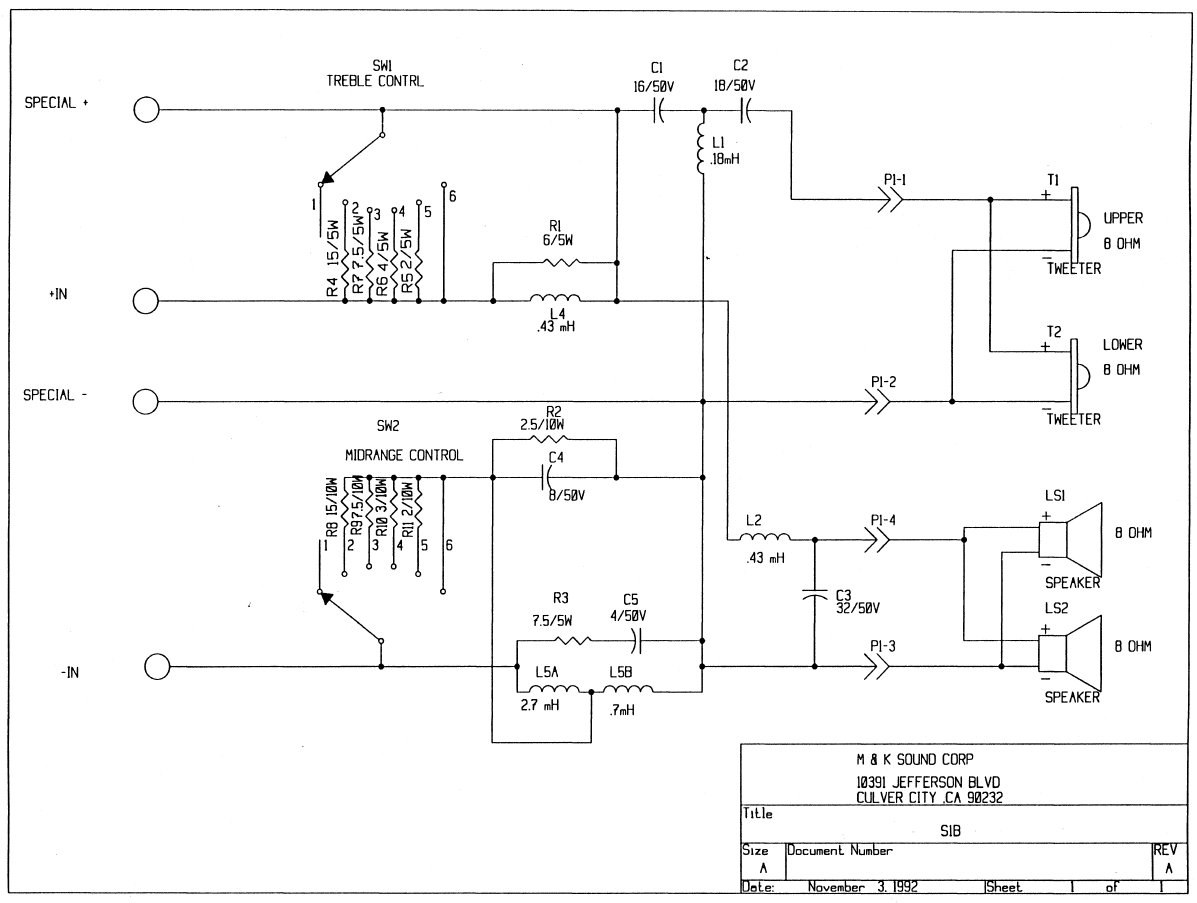
It may help to understand it with a little more background.
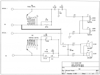
M&K sold an external control module for these speakers in professional situations. When you used it, you were to use the Special inputs (+ and -)
But for home, the normal connections were used (IN+ and IN-)
Think of the Special inputs as bypassing the EQ sections and using only the HP and LP filters. You can see this way that even with switches set to bypass there is still some extra EQ being applied.
So, the actual crossover is a very simple 3rd order HP and 2nd order LP. Everything else is EQ.
Last edited:
After looking at the shaping curves, I really might now do a lot of upgrading here. I'd be seriously tempted to do a white paper design instead.
OP, you might also want to try listening via the Special inputs, instead. I'd be really curious to know how that sounds to you.
Best,
E
OP, you might also want to try listening via the Special inputs, instead. I'd be really curious to know how that sounds to you.
Best,
E
OK, I think I see a couple of mistakes in the schematic. Of course, it may not be, but this is how this now makes a lot more sense:

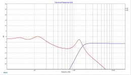
I've simulated this a little using XSim, with ideal tweeters and 5" Peerless woofers I happen to have data for. The range of values make a lot more sense now. The midrange contol causes a broad depression centered around 500-700 Hz and the treble control acts like a volume control, and the levels blend much better.
The tweeter level adjusts from 0 to about -6 dB, again, given ideal drivers, YMMV given actual tweeter impedance curves.
Here is a pic of the transfer function with the adjustment resistors shorted:
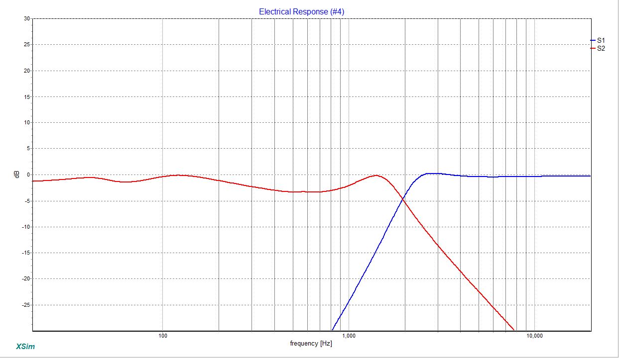
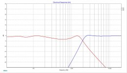
As well as using the maximum resistance:

I've simulated this a little using XSim, with ideal tweeters and 5" Peerless woofers I happen to have data for. The range of values make a lot more sense now. The midrange contol causes a broad depression centered around 500-700 Hz and the treble control acts like a volume control, and the levels blend much better.
The tweeter level adjusts from 0 to about -6 dB, again, given ideal drivers, YMMV given actual tweeter impedance curves.
Here is a pic of the transfer function with the adjustment resistors shorted:
As well as using the maximum resistance:
Attachments
Last edited:
It's all down to the Laws of Physics, in the end, I feel.
We know that Classical Mechanics is wrong. UberGeek Sidney Coleman proved that: YouTube
For all that, Classical Mechanics holds some surprises: Orbital resonance - Wikipedia

Nature throwing up a sort of exact 1:2:4 resonance. In fact the common Wiki approach lacks mathematical rigour. Precession of axes (the perigee) plays a part. We mere monkeys lack a deeper understanding of rotation. In multi-dimensions, 4D upwards, rotation is about a plane, not an axis. The axis is a purely 3D phenomena. And since we live in a a 4D spacetime, I'm not betting my life on the axis.
What I find fascinating is that in the proveably correct Quantum Theory lurks a half-unit of information. What does that mean? Simply that an Electron might have a spin half up, or half down. Or however you measure it, it is opposite to its other half. The Local Schrodinger Cat is either dead or alive. The other one is the opposite.
We know that Classical Mechanics is wrong. UberGeek Sidney Coleman proved that: YouTube
For all that, Classical Mechanics holds some surprises: Orbital resonance - Wikipedia
Nature throwing up a sort of exact 1:2:4 resonance. In fact the common Wiki approach lacks mathematical rigour. Precession of axes (the perigee) plays a part. We mere monkeys lack a deeper understanding of rotation. In multi-dimensions, 4D upwards, rotation is about a plane, not an axis. The axis is a purely 3D phenomena. And since we live in a a 4D spacetime, I'm not betting my life on the axis.
What I find fascinating is that in the proveably correct Quantum Theory lurks a half-unit of information. What does that mean? Simply that an Electron might have a spin half up, or half down. Or however you measure it, it is opposite to its other half. The Local Schrodinger Cat is either dead or alive. The other one is the opposite.
I guess I'm not getting my email notifications.
Erik, from what I have read, I'm not supposed to run into special inputs direct from amp, or in my case, the sub. I'm pretty sure they are for using the external control box M&K sold.
My goal for these speakers is still the same, which is replacing caps and resistors. That's doable for me at this point. The coils look good, and as I mentioned earlier, the speakers sound good as they are. I'm just wanting to be freshened up for the next 10+ years, and be able to use the contour controls to experiment in my new listening environment.
At the very least, I can easily find replacement NP electrolytic caps of good quality that are affordable (to me) ... but if I decide to go with Mills wire wound to replace the cement resistors, I see the ohm values don't match. I know I can use the next higher voltage rating. Then there is the matter of why the stock resistors were glued together, which I wouldn't do on the Mills ... but wondering if there is a minimum amount of space needed between them.
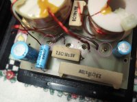
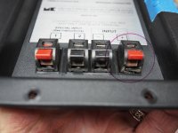
Lastly, I can't figure out how to get the pcb's off the panel. I'm guessing, but need confirmation, that I have to remove the solder on the speaker terminals, shown in the photo below. I broke a small piece off one terminal that fortunately doesn't effect it's function, but being picky about stuff like that, I may want to find a clean replacement for both speakers, since the same terminal on the other speaker had the same piece missing, which I'm guessing the previous owner may have tried to remove, and once it broke, gave up and sold to me?
Erik, from what I have read, I'm not supposed to run into special inputs direct from amp, or in my case, the sub. I'm pretty sure they are for using the external control box M&K sold.
My goal for these speakers is still the same, which is replacing caps and resistors. That's doable for me at this point. The coils look good, and as I mentioned earlier, the speakers sound good as they are. I'm just wanting to be freshened up for the next 10+ years, and be able to use the contour controls to experiment in my new listening environment.
At the very least, I can easily find replacement NP electrolytic caps of good quality that are affordable (to me) ... but if I decide to go with Mills wire wound to replace the cement resistors, I see the ohm values don't match. I know I can use the next higher voltage rating. Then there is the matter of why the stock resistors were glued together, which I wouldn't do on the Mills ... but wondering if there is a minimum amount of space needed between them.
Lastly, I can't figure out how to get the pcb's off the panel. I'm guessing, but need confirmation, that I have to remove the solder on the speaker terminals, shown in the photo below. I broke a small piece off one terminal that fortunately doesn't effect it's function, but being picky about stuff like that, I may want to find a clean replacement for both speakers, since the same terminal on the other speaker had the same piece missing, which I'm guessing the previous owner may have tried to remove, and once it broke, gave up and sold to me?
Attachments
I guess I'm not getting my email notifications.
Erik, from what I have read, I'm not supposed to run into special inputs direct from amp, or in my case, the sub. I'm pretty sure they are for using the external control box M&K sold.
Exactly as I stated above. It doesn't explain the schematic fully, so I think there were some mistakes, which is VERY common.
My goal for these speakers is still the same, which is replacing caps and resistors. That's doable for me at this point. The coils look good, and as I mentioned earlier, the speakers sound good as they are. I'm just wanting to be freshened up for the next 10+ years, and be able to use the contour controls to experiment in my new listening environment.
At the very least, I can easily find replacement NP electrolytic caps of good quality that are affordable (to me) ... but if I decide to go with Mills wire wound to replace the cement resistors, I see the ohm values don't match. I know I can use the next higher voltage rating. Then there is the matter of why the stock resistors were glued together, which I wouldn't do on the Mills ... but wondering if there is a minimum amount of space needed between them.
Lastly, I can't figure out how to get the pcb's off the panel. I'm guessing, but need confirmation, that I have to remove the solder on the speaker terminals, shown in the photo below. I broke a small piece off one terminal that fortunately doesn't effect it's function, but being picky about stuff like that, I may want to find a clean replacement for both speakers, since the same terminal on the other speaker had the same piece missing, which I'm guessing the previous owner may have tried to remove, and once it broke, gave up and sold to me?
Gluing was usually done to prevent shipping damage. Those big resistors are heavy, so when they vibrate they carry a lot more kinetic energy than little SMD or 1/8 Watt resistors. You should snip them at the PCB, measure, and then use a hot air gun to soften the glue, with a broad blade to help you pull them off the board. Think chisel or putty knife. Then you can de-solder the ends.
Those big speaker connectors need a big *** solder gun. I use a temperature controlled one with a broad soldering tip. Your average solder wand just will not work.
I think replacing all the caps is a good idea, but if you want to get fancy, C1/C2 are the items to upgrade.
Best,
E
Also, you don't necessarily need to replace every resistor there around the switches. Truth is those are set and forget.
Personally, I would bypass the switch entirely, reducing the possibility of arcing and added resistance through a dirty switch. Later models used SPDT type switches instead.
Best,
E
Personally, I would bypass the switch entirely, reducing the possibility of arcing and added resistance through a dirty switch. Later models used SPDT type switches instead.
Best,
E
I use a Hakko FX-888D with T18-D24 chisel tip.
I normally don't replace resistors when they are functioning, unless there is a sonic benefit, so if you are suggesting I just leave those alone, I can do that. It's not like I can't come in later to update those, but my plan is to do this once on these.
I appreciate your suggestion of bypassing the switch, but since there is a chance I will move these on down the road, I feel it's important to keep that functionality. Call me old fashioned.
So two last questions. Were you confirming that I need to remove the solder on those speaker terminals at the pcb to remove?
Do you have recommendations on C1/C2 ?
Thanks for your time and help!
I am pretty sure yes, you need to remove the speaker terminal solder.
For the size, Mundorf MKP are really hard to beat. I prefer Clarity, but again, physical size is a limiting factor.
You could also try replacing with a bi-polar electrolytic, leaving the last uF or so film.
Best,
E
For the size, Mundorf MKP are really hard to beat. I prefer Clarity, but again, physical size is a limiting factor.
You could also try replacing with a bi-polar electrolytic, leaving the last uF or so film.
Best,
E
Yeah, I wondered about that. Those are some odd values. Still, that's an advantage. YOu can find 15uF, and add 1uF in film to get 16, or add 3.3uF to get 18.3uF (close enough)
You just hit on a point I was going to ask about. Is there a variation to ohm rating that is acceptable, or universally agreed that it will not negatively effect sound quality? And if so, I assume that it's better to be "just over" the stock value as opposed to "just under". Sorry for all the questions, but this is helpful for me to learn.
I have been looking at a few different online shops and I may end up buying from two places, which I wanted to avoid paying shipping twice. Parts Express has some cheap Audyn Cap Q4 1.0uF 400V MKP for only $1.77 each
Audyn Cap Q4 1.0uF 400V MKP Metalized Polypropylene Foil Crossover Capacitor
... of course, they are almost three times the size of the stock value caps in there now, but if the leads are long enough, I might be able to set on top of NPE's and put wire insulation on the leads.
Caps are in microfarads, not Ohms. Written with a mu ( like a little u ) and an F.
I try to get as close as I can, but look at the cap values. Usually there will be a tolerance, like 5%.
That tells you the caps are +- 5% and you can use that as a guide. Many like Audyn, just keep an eye on physical size!
Best,
E
I try to get as close as I can, but look at the cap values. Usually there will be a tolerance, like 5%.
That tells you the caps are +- 5% and you can use that as a guide. Many like Audyn, just keep an eye on physical size!
Best,
E
- Status
- This old topic is closed. If you want to reopen this topic, contact a moderator using the "Report Post" button.
- Home
- Loudspeakers
- Multi-Way
- Miller & Kreisel S-1B satellite crossover update